Defender (1993+). Manual — part 61
REAR
AXLE AND FINAL DRIVE
REAR AXLE AND FINAL DRIVE
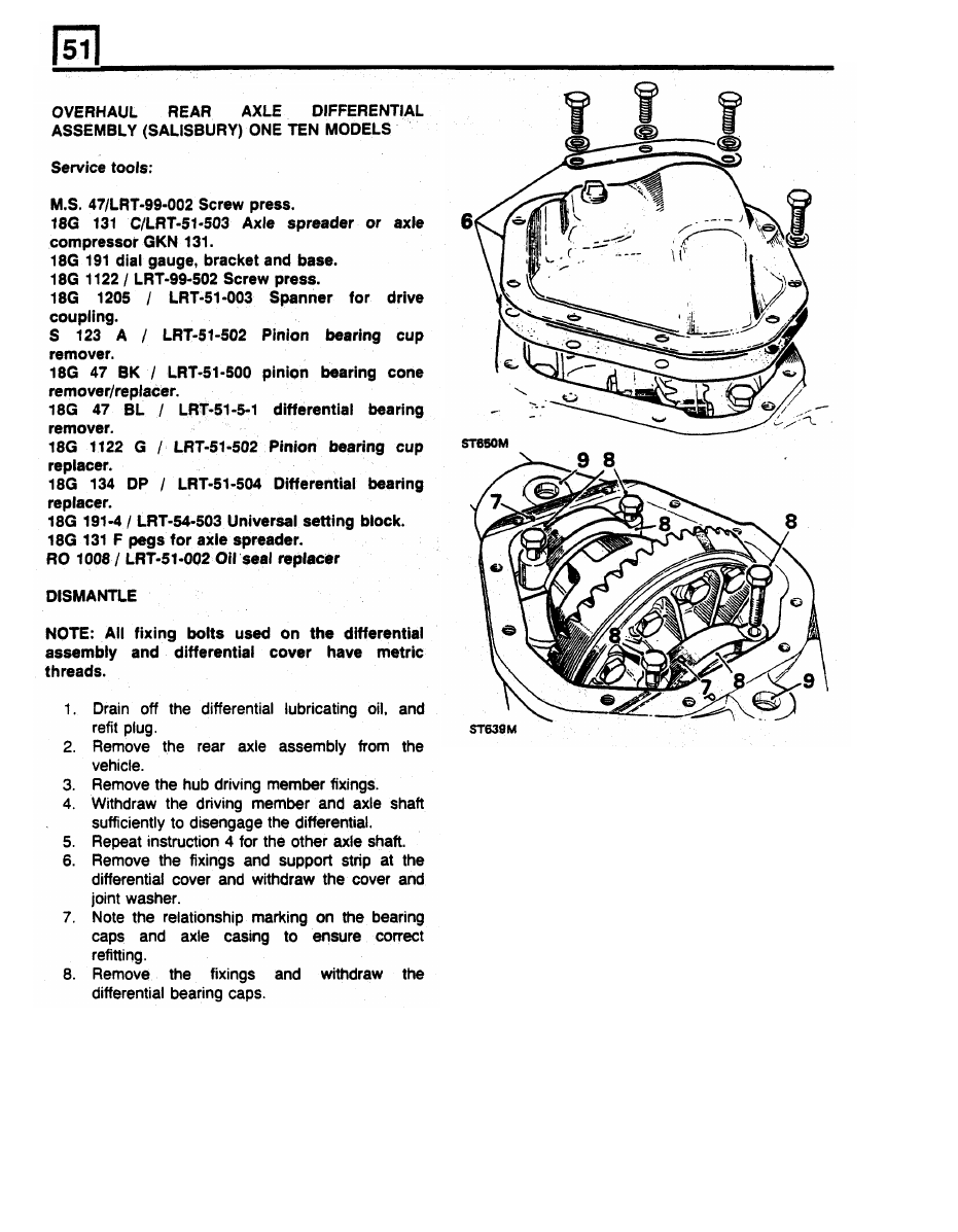
CAUTION:
To prevent permanent damage to the
gear carrier case,
it
must not
be
over-stretched.
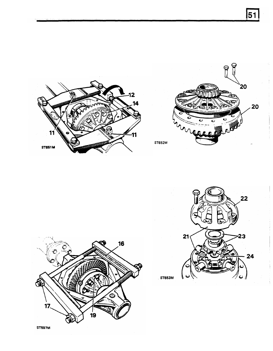
Each flat on the turnbuckle
is numbered to
20. Add alignment marks between the crown
enable
a check to be made on the amount
wheel and the differential case for reassembly
turned. The maximum stretch permitted
is 0,30
purposes, then remove the fixings and
mm, equivalent to three flats.
Dismantle differential
withdraw the crown wheel.
15.
Ease off the adjuster and remove the
spreader.
21.
Note the alignment markings on the two
differential casings
to
ensure correct refitting,
then remove the fixings.
22.
Lift
off the upper case.
16.
Place the tool on to the differential casing, as
23. Withdraw the upper differential wheel and
thrust washer.
illustrated,
with
the weld seam uppermost.
Ensure that the plates rest squarely on the
differential machined surface and the end bars
butt against the edges of the casing.
17.
Tighten the adjusting nuts by hand only, until
all slack is taken up.
18.
Continue to tighten both nuts alternately with a
spanner, one flat at a time, to a maximum of
three flats.
19.
Carefully lever-out the differential assembly.
Using axle compressor GKN 131
24. Lift out the cross-shaft and pinions.
25. Withdraw the four dished thrust washers.
26. Withdraw the lower differential wheel and
thrust washer.

REAR
AXLE AND FINAL DRIVE
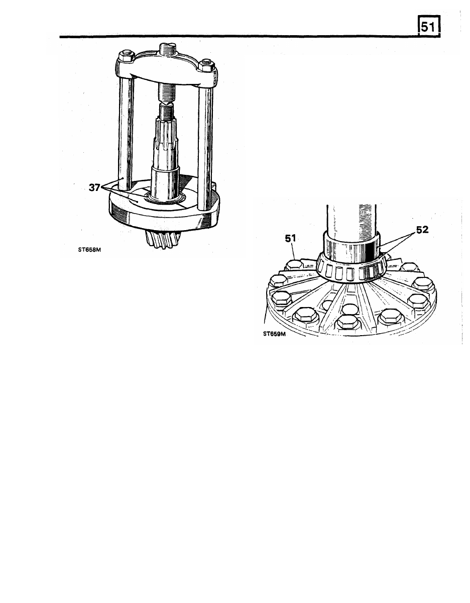
34. Withdraw the outer bearing cone.
27. Remove the differential bearing cones using
35. Extract the pinion inner bearing cup and shim
remover 18G 47 BL and adaptors 1 and 2 and
washers from the casing. Note the shim
press M.S. 47.
washer thickness using remover S 123 A.
28. Withdraw the shim washers fitted between the
36. Extract the pinion outer bearing cup from the
bearing cones and the differential casings.
casing using remover S 123 A.
37. Remove the inner bearing cone from the
pinion, using remover 18G 47 BK and press
M.S. 47.
Remove final drive pinion
29. Prevent the coupling flange from rotating and
remove the flange
locknut and plain washer
using tool 18G 1205.
30. Support the drive pinion and remove the
coupling flange by tapping with a hide
hammer.
31. Withdraw the drive pinion together with
the
inner bearing cone.
32. Withdraw and discard the collapsible bearing
spacer.
33.
Withdraw the oil seal, gasket and oil thrower.
R E A R
AXLE
AND
FINAL
DRIVE
50.
Secure the assembly with bolts using Loctite
'Studlock' grade CVX on the threads and
tighten evenly and diametrically to
89
to 101
Nm.
51.
Fit the crown wheel to the differential casing.
Use Loctite 'Studlock' grade
CVX on the fixing
bolt threads and tighten to
the correct torque.
52. Press on the differential roller bearing cones
less him washers, using 18G 134
DP, and
leave to one side until required for instruction
53. Fit the
bearing cups
to
the differential.
54. Fit the differential unit and bearings to the
gear
carrier casing,
and
rotate
unit
to
centralize the bearings. Do not
fit
the bearing
caps.
INSPECTION
38. Examine all components for obvious wear or
damage.
39. The bearing cones must be a press fit on their
locations, except the drive pinion flange and
bearing which is a slide fit.
40. The crown wheel and pinion are supplied as a
matched pair and must not be interchanged
A new crown wheel and pinion matched pair
may be fitted to an original gear carrier casing
if sound. The original crown wheel and pinion,
if sound, may be fitted into a replacement
casing.
41. The two parts of the differential unit casing
are matched and must not be replaced
separately.
42. Discard and renew all thrust washers.
43. Differential housings with worn thrust washer
seatings must be replaced as a pair.
44. Examine the differential case to crown wheel
joint face for burrs and damage which could
lead to crown wheel run-out when fitted.
separately.
55.
Position a suitable dial gauge indicator on the
casing with the stylus registering on the back
face of the crown wheel.
56.
Rotate the differential and check the total
indicated run-out on the crown wheel back
face. This must not exceed 0,05 mm. If
run-out is excessive, check the mating faces
for dirt and damage: if necessary, select a
new radial position for the crown wheel. When
satisfactory, continue with the following check.
Differential bearing adjustment
57.
Insert
two
levers between the casing and the
differential unit at one side.
ASSEMBLE
58.
Move the differential unit fully
to one side of
the casing; do not
tilt
the unit.
Assemble differential unit
59. Rotate the differential unit to settle the
bearings, continue to lever the differential to
the side, then zero the dial gauge indicator.
60. Lever the assembly
fully to
the other side
of
the casing, rotate the unit
to
settle the
45. Fit the differential lower wheel and thrust
washer to the differential case. See illustration
following instruction 23.
46.
Fit the dished thrust washers.
bearings, then note the
total
indicator reading.
47.
Fit the cross-shaft and pinions.
48.
Fit the differential upper wheel and thrust
washer.
49.
Fit the differential upper case lining-up the
96.
Нет комментариевНе стесняйтесь поделиться с нами вашим ценным мнением.
Текст