Defender (1993+). Manual — part 62
REAR AXLE AND FINAL DRIVE
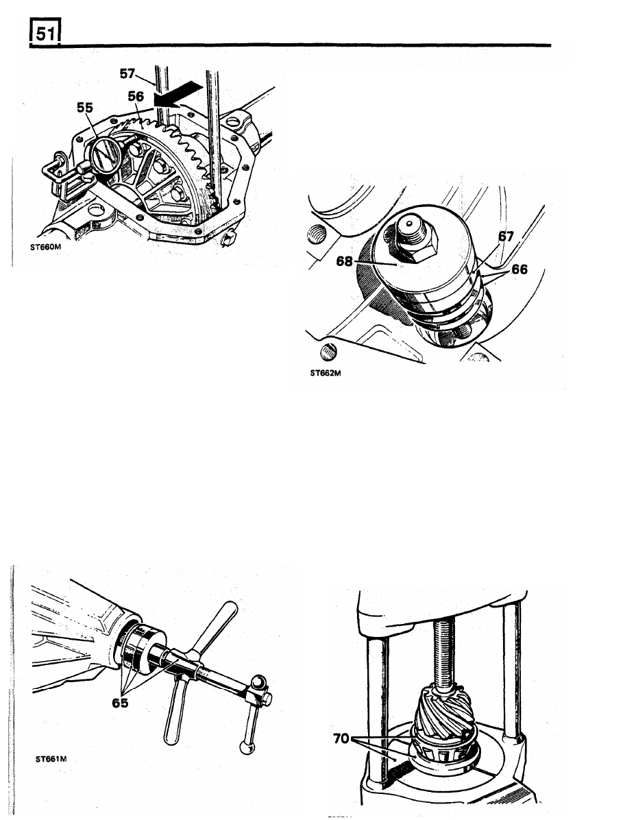
66. Place the selected shim washers on
to
the
inner bearing cup seating.
67. Position the inner bearing cup in
the
casing.
68. Position the inner bearing replacer 18G
11
22
G
detail
1,
onto 18G 1122 and secure with
the fixing nut.
69.
Hold still the centre
screw and turn the
butterfly lever
to draw in the bearing cups.
61. Add 0,127 mm, for bearing pre-load, to the
total noted in the preceding instruction. The
sum is then equal to the nominal value of
shims required for the differential bearings:
Shims are available in the range 0,07 mm,
0,12 mm, 0,25 mm and
0,76
mm. Select the
total value of shims required.
62. Remove the differential unit and bearings and
place aside.
Do not fit the shim washers until
the
subsequent 'Differential backlash' checks
have been made, instructions 96 to 102.
70. Press the inner bearing cone onto the drive
pinion using 18G
47
BK, details 1 and 2 and
press
MS
47.
71. Position the pinion and bearing in the casing;
omit the collapsible spacer at this stage.
72. Fit the outer bearing cone onto the pinion.
73. Fit the coupling flange and plain washer and
loosely fit the flange nut.
74. Tighten the coupling flange locknut to remove
end-float from the pinion.
75. Rotate the pinion to settle the bearings and
slowly
tighten the flange locknut. Use a spring
balance to obtain a torque resistance of 9,25
to 13,8 kgf cm. to rotate the pinion.
Fit drive pinion
63.
Select shim washers
of
the same thickness
value as those removed from under the pinion
inner cup, instruction 35, and place ready for
fitting,
64. Position the outer bearing replacer
18G 1122
G detail 2, and the outer bearing cup en the
press tool 18G 1 122.
65.
Locate the assembly into the pinion housing
nose.
REAR
AXLE AND
FINAL DRIVE
Drive pinion
markings
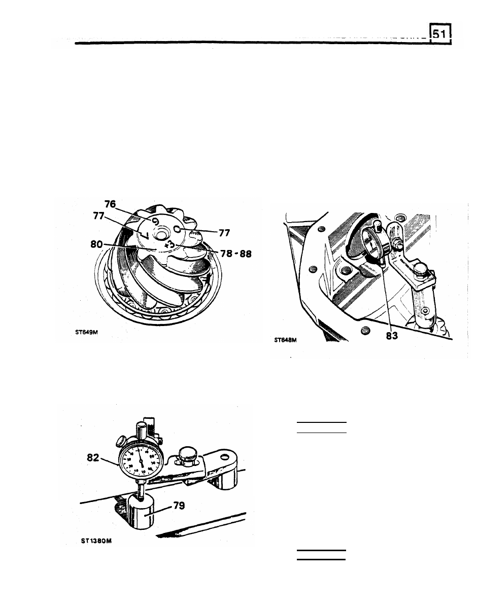
81. Remove the keep disc from the magnetized
base
of
dial gauge tool
18G191
76. Check that the serial number marked on the
82.
Place the dial gauge and setting gauge
pinion end face matches that marked on the
18G191P or 18G191-4 on a
fiat
surface and
crown wheel.
zero the dial gauge
stylus
on to
the setting
77.
The markings on the end face adjacent to the
gauge.
serial number are
of
no significance during
83.
Position the dial gauge centrally on the pinion
servicing.
end face
with
the stylus registering on the
78.
The figure marked on the end face opposite to
lowest point on one differential bearing
bore.
the serial number indicates, in thousandths
of
Note the dial gauge deviation from the zeroed
an
inch, the deviation
from nominal required to
correctly set the pinion. A pinion marked plus
84.
Repeat on the other bearing bore. Add
(+) must be set below nominal, a minus
(-)
together the readings, then halve the sum to
pinion must be set above nominal. An
obtain the mean reading. Note whether
the
unmarked pinion must be set at nominal.
stylus has moved up
or
down
from
the zeroed
setting.
setting.
79.
The nominal setting dimension is represented
by the setting gauge block 18G191P or
Example 1
18G 191 -4, which is referenced from the pinion
end face
to the bottom radius
of
the
Reading obtained L H side
+
0.006in
differential bearing bore. The latter gauge
I
S
Reading obtained R H side
- 0.003in
illustrated following instruction
85.
Add
+
0.006in
- 0.003in
+
0.003in
Divide by 2 (0.003in divided by 2)=
0.0015in
Therefore subtract
0.0015in
from the shim thickness
behind
the pinion inner bearing track
Example 2
Reading obtained
L H side
+
0.006in
Reading obtained
R H side
- 0.008in
Add
+
0.006in
- 0.008in
- 0.002in
Drive pinion adjustment
I
80.
Ensure that the pinion end face is free of
raised burrs around the etched markings.
Divide by
2
(0.002in divided by
2)= 0.001in
Therefore add
0.001in from
the shim thickness
behind the pinion inner bearing
track
REAR AXLE
AND FINAL DRIVE
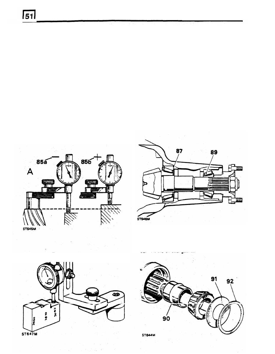
85. Where the stylus has moved down (85a), the
86. Before adjusting the shim thickness, check the
amount is equivalent
to
the thickness of shims
pinion face marking and
if
it
has a plus
(+)
that must be removed from under the pinion
figure, subtract that from the shim thickness
inner cup
to
bring the pinion down
to
the
figure obtained in the previous instruction
nominal position. Where the stylus has moved
Alternatively
if
the pinion has a minus
( - )
up (85b), the amount
IS
equivalent
to
the
figure, add the amount
to
the shim thickness
additional thickness of shims required
to
bring
figure.
the pinion up
to
the nominal position.
87. Adjust the shim thickness under the pinion
inner cup as necessary, by the amount
Illustration
A.
Using setting gauge 18G191P.
determined in instructions
85
and
86.
88. Recheck the pinion height setting instructions
illustration
B.
Using
universal
setting
block
82
to
84. If
the setting is correct, the mean
18G
191
-4.
This setting block has three setting
reading on the dial gauge
will
agree
with
the
heights as follows:
figure marked on the pinion end face
For
example, with an end face marking of +3, the
39.50 mm Rationalised axle
dial gauge reading should indicate that the
38.10 mm Pre-Rationalised axle
pinion is 0.003 in
(0.0762
mm) below nominal.
30.93 mm Salisbury axle
89. When the pinion setting is satisfactory,
temporarily remove the pinion outer bearing.
Ensure that the height marked
30.93
mm is used for
this differential.
90. Fit a new collapsible bearing spacer, flared
end outward, to the drive pinion and refit the
outer bearing.
91. Fit the pinion oil slinger.
92. Fit the oil seal gasket.
REAR AXLE
AND FINAL
DRIVE
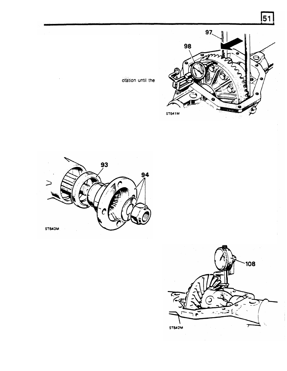
93.
Fit the pinion oil seal, lipped side first, using
general purpose grease or, where available, a
molybdenum disulphide based grease on the
seal lip, using
RO
1008 to drift in the seal.
94.
Fit the coupling flange and plain washer and
loosely
fit
a new flange nut. Secure
18G 1205
to
the coupling flange, using slave fixings.
95. Alternately tighten the flange nut and check
the drive pinion resistance to r
following figures are achieved, as applicable:
a. Assemblies
re-using
original
pinion
bearings: 17,3 to 34,3 kgf cm.
b. Assemblies with new pinion bearings: 34,5
to 46,0
kgf cm.
NOTE: Once the bearing spacer has started to
collapse the torque resistance build-up is rapid,
therefore check frequently, using a spring
102. Fit the shim value determined in instruction
101, taking the shims from the pack
balance, to ensure the correct figures are not
previously determined during 'Differential
exceeded, otherwise a new collapsible bearing
bearing adjustment' checks, instructions 57 to
spacer
will
be required.
62
18G 47 BL details 1 and
2,
using press NS
47 and 18G 134
DP.
103. Fit the remaining shims
from
instruction
101
to
the opposite side of the differential, using 18G
47
BL
details 1 and 2, press MS 47 and 18G
134 DP.
104. Fit the differential unit with shims and
bearings to the axle casing, using the axle
spreader 18G 131
C
with pegs 18G 131 F.
105. Remove the axle spreader.
106. Fit the bearing caps in their correct position,
referring
to
the relationship markings on the
caps and on the axle casing.
107. Tighten the bearing caps fixings to 126 to 142
Nm.
108. Mount a dial gauge
on
the axle casing
with
the stylus resting on a crown wheel tooth.
Differential backlash
checks
96. Pick up the differential unit as left after
instruction 52.
97. Fit the differential unit and lever the unit away
from the drive pinion until the opposite bearing
cup is seated against the housing. Do not tilt
the unit.
98. Install a dial gauge on the casing with its
stylus resting on the back face of the crown
wheel. Zero the gauge.
99. Lever the differential unit to engage the crown
wheel teeth in full mesh with the drive pinion
teeth. Do not tilt the unit.
100. Note the total reading obtained on the dial
gauge.
correct crown wheel backlash when fitted. The
result indicates the value of shimming to be
fitted between the differential case and the
bearing cone at the crown wheel side of the
differential.
101. From this figure subtract 0.010 in to obtain
Нет комментариевНе стесняйтесь поделиться с нами вашим ценным мнением.
Текст