Defender (1993+). Manual — part 28
RO.1014
RO274401
ENGINE
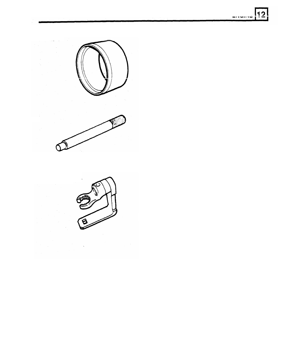
LRT-12-010
Crankshaft rear seal sleeve
RO1014
LRT-12-037
Drift for valve guide removal
-
intake and
RO274401A
exhaust
LRT-12-047
Torque adaptor lambda sensor
LST134
LST134
EMISSION CONTROL
The purpose
of
the crankcase ventilation system is
to
ensure that any noxious gas generated in the
Three systems are used to control the vehicle
engine crankcase
is
rendered harmless by burning in
atmospheric emissions these are:
the combustion chambers as follows:
Oil laden noxious gas in the engine crankcase is
Engine crankcase fume emissions.
drawn through an oil separator
3
located on the right
Fuel tank Evaporative emissions
cylinder head rocker cover, where the oil is
Engine exhaust gas emissions.
separated and returned to the stump. The gas flows
through a restrictor
in
the three way connection
1
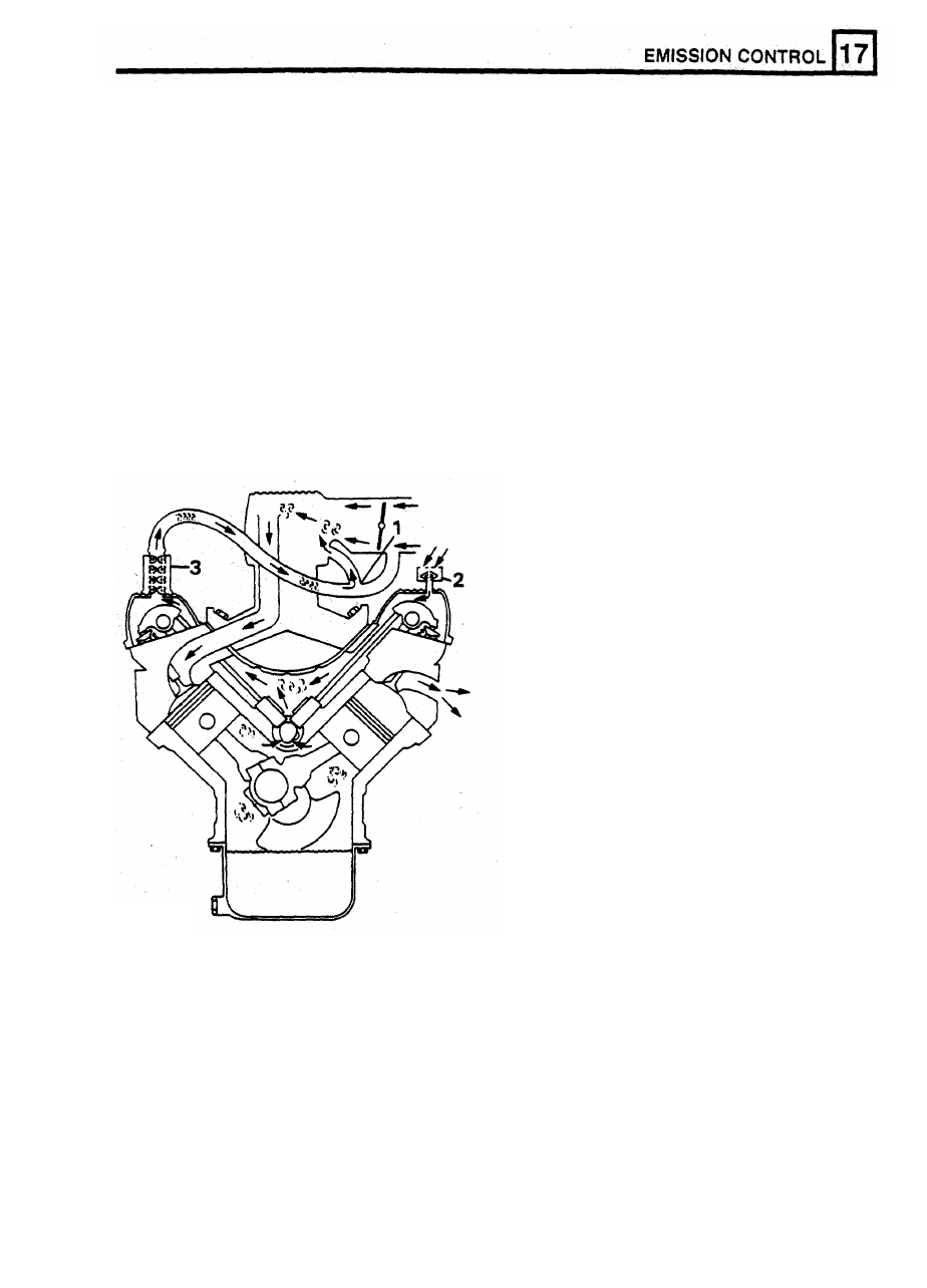
Crankcase ventilation system
and into the inlet plenum chamber where it drawn
into the combustion chambers and burned. The
The crankcase ventilation system which is an
volume of fresh air which
is
drawn from the
integral part of the air supply
to
the engine
atmospheric side
of
the throttle butterfly to mix with
combustion chambers, is often overlooked when
the gas, depends on the position
of
the throttle and
diagnosing
problems
associated
with
engine
the engine speed.
performance.
A
blocked ventilation pipe or filter or
excessive air leak into the inlet system through a
The air filter
2
fitted
to
the left cylinder head rocker
damaged pipe or leaking gasket can effect the
cover, must be maintained in clean condition to
mixture, performance and economy of the engine.
ensure sufficient air enters the crankcase under
varying throttle openings and manifold depression, to
prevent excessive crankcase pressure or depression
developing.
1
Three way connector
2
Air filter
3 Oil separator
REISSUED:
FEB
1993
1
RR3534M
E MISSION
CONTROL
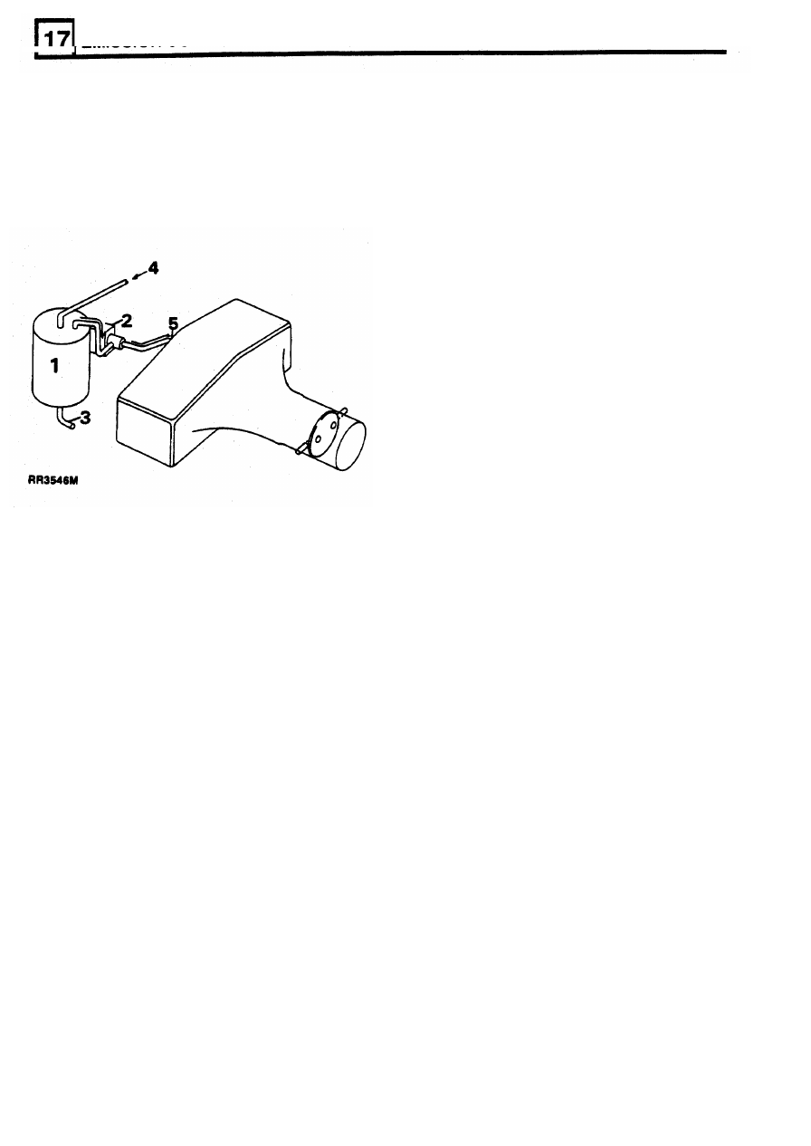
EVAPORATIVE EMISSION CONTROL
The opening of the purge valve (2), which
I
S
controlled by the MFI ECM occurs when the
Fuel tank evaporative control
following conditions prevail:
The specification for certain countries requires the
When the engine is running at speeds above
recycling
of
petrol evaporation from the fuel tank. For
1700 rev/min and temperatures above 54°C the ECM
these countries only, a charcoal canister and purge
will hold open the purge valve as necessary.
valve are installed in the engine compartment.
At
speeds below 1700 rev/min the ECM will only
pulse the purge valve open for short periods.
While the purge valve (2) is open, engine depression
draws air through vent
(3)
and fuel tank fumes via
(4)
into the engine combustion chambers, where they
are burned. Air entering at (3), passes through the
charcoal, where any accumulation of condensed fuel
is also extracted and burned in the engine.
A permanent leakage of air into the plenum
chamber through the purge system will effect
engine performance.
Fuel tank evaporative control system
The system consists of a fuel separator/expansion
tank located at a higher level than the fuel tank,
between the inner body side and the right rear
fender. The tank is vented to atmosphere through
a
relief valve and is connected
to the fuel tank and the
charcoal canister purge system in the engine
Evaporative purge system
1
Charcoal canister
compartment.
2
Purge valve
3
Charcoal canister air vent
4. Fuel purge connecion from
separator/expansion tank
5
Plenum chamber connection
Operation
When the engine is not running, the purge valve
(2)
seals the plenum
chamber
connection
(5).
Any
vapour
entering
the
canister
at
(4)
from
separator/expansion tank, is condensed by the air
entering at
(3)
which is then
absorbed
by the
charcoal.
2
REISSUED: FEB 1993
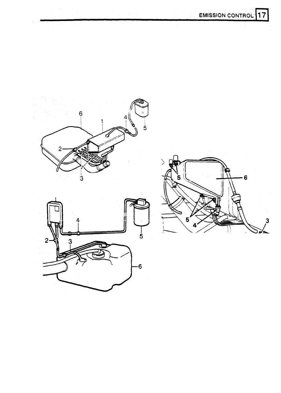
Operation
FUEL EXPANSION TANK
As
the temperature rises, fuel vapour in the fuel tank
IS
allowed
to
vent into the separator/expansion tank
(1)
via three pipes and a manifold connector
(3).
Any
vapour which condenses into liquid fuel drains
WARNING:
Ensure all necessay precautions are
through pipe
(6)
back into the main fuel tank and
taken against spillage of fuel when disconnecting
residual vapour is dealt with by the purge system
expansion tank hoses.
connection
(4)
in the engine compartment.
The atmosphere relief valve
(2)
will only open if a
DEFENDER 110
blockage occurs in the charcoal canister
or
purge
system.
Remove
The fuel expansion tank is located under the wheel
arch of the right rear fender.
1.
Loosen fuel tank filler cap
to
release any
2.
Disconnect battery negative lead.
3.
Disconnect pipe connection at joint under
chassis member.
4.
Disconnect evaporative control pipes. Use
LRS-19-002, press down on collet and pull
connector.
pressure in tank.
ST3416M
Defender 110
ST3417M
ST3460M
5.
Remove
four nuts
and remove expansion
tank.
Refit
6.
Reverse removal instructions.
Defender 90
Fuel tank evaporative control system
1
Fuel
expansion tank
2 Relief
valve
to
atmosphere
3
Fuel tank vent
4
Relief valve to charcoal canister
5
Charcoal Canister
in
engine compartment
6
Fuel tank
REVISED:
OCT
1993
3
Нет комментариевНе стесняйтесь поделиться с нами вашим ценным мнением.
Текст