Defender (1993+). Manual — part 82
BRAKING
SYSTEM
20. The shoes in the wheel cylinder piston slots
2.
Disconnect the propeller shaft from the output
and lever the opposite ends into the pivot
flange.
block.
3.
Remove the two screws and withdraw the
21. Operate the snail cams
to
check that the
brake drum. Skim if excessively scored or
shoes respond.
oval.
22. Connect the brake fluid pipe to the wheel
4. Remove the split pin and clevis pin connecting
cylinder.
23. Fit the brake drum and secure with the single
5.
Remove the brake shoes complete with
screw.
pull-off springs. Note position of springs in
24. Adjust each brake shoe independently as
relation to the shoes.
follows:
turn one adjuster until the shoe is
6. Remove the four bolts securing back-plate to
locked
against
the
drum.
Back
off
transfer box and withdraw the back-plate
approximately
two
serrations of the snail cam
complete with oil catcher.
so
that the drum revolves freely.
25. Repeat instruction 24 on the second shoe and
carry out the same procedure for the opposite
brake.
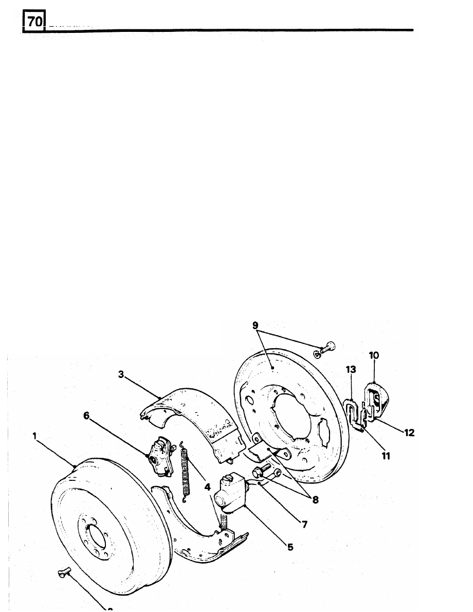
1.
Brake drum.
26. Bleed the brakes.
2. Brake drum retaining screws
27. Fit the road wheels, remove the axle stands
3. Brake shoes.
4. Brake shoes pull-off springs.
6.
Adjuster assembly.
8. Oil catcher.
9. Back plate and retaining bolts.
10. Dust cover.
the drawlink to the actuating lever.
KEY
TO
TRANSMISSION BRAKE
and finally tighten the road wheel nuts to the
correct torque.
5.
Expander assembly.
OVERHAUL TRANSMISSION BRAKE
7. Draw link.
WARNING:
Do
not use an air line to remove dust
from the brake assembly. Asbestos dust from the
brake linings can
be
a serious health risk, if
11. Locking plate.
inhaled.
12. Packing plate.
DISMANTLING
13.
Spring plate.
1.
Disconnect the battery and chock the road
wheels for safety.
BRAKING SYSTEM
Remove and overhaul expander assembly
7.
Remove the rubber dust cover.
8.
Remove the expander and draw link.
9. Remove the retainer spring plate.
10. TDO106,254,254 Remove the locking plate.
11. Remove the packing plate and withdraw the
expander assembly from the back-plate.
12. Remove the two plungers and rollers.
13. Clean all parts in Girling cleaning fluid and
allow to dry. Examine the components for
wear and discard if unsatisfactory.
Assemble expander assembly
14. Grease and fit the expander and drawlink.
15. Grease and fit the plungers and rollers noting
that the highest end o f the ramp on the
plungers is fitted towards the back-plate.
Secure the assembly band to
one side for assembly
to
back-plate.
ASSEMBLE
NOTE:
If
the brake linings are oil-soaked check
prevent the plungers falling out and place to
and if
necessary renew the
output shaftoil
seal.
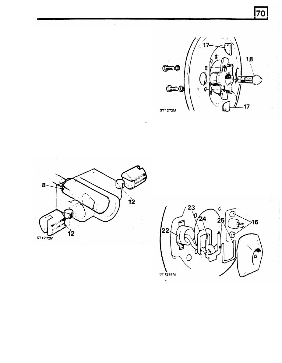
22. Position the expander assembly on the inside
of
the back-plate and secure with the following
plates at the rear of the back-plate.
23. Locking plate.
24. Retaining plate.
25. Packing plate.
26. Fit the rubber dust cover.
Remove and overhaul adjuster assembly
16.
Remove the two bolts and withdraw the
adjuster assembly from
the
back-plate.
17.
Remove the plungers.
18. Screw the adjuster cone inwards
to
remove
from the housing.
discard any unsatisfactory components.
19. Clean the parts in Girling cleaning fluid and
27. Fit the adjuster assembly to the back-plate
with the two bolts but do not fully tighten at
this stage.
28. Fit the back-plate assembly and mud shield to
the transfer box with the four bolts and tighten
to
the correct torque.
and
fit
to
the back-plate. Note that the fully
lined end of the lower shoe must be toward
the expander assembly and the fully lined end
of the upper shoe towards the adjuster
assembly.
Assemble adjuster assembly
20. Grease and screw in the adjuster cone.
the chamfered ends with the adjuster cone.
Note that the two plungers are identical and
can be fitted to either bore. Secure the
assembly with a rubber band
to
prevent the
plungers falling out.
21. Grease and
fit
the adjuster plungers and align
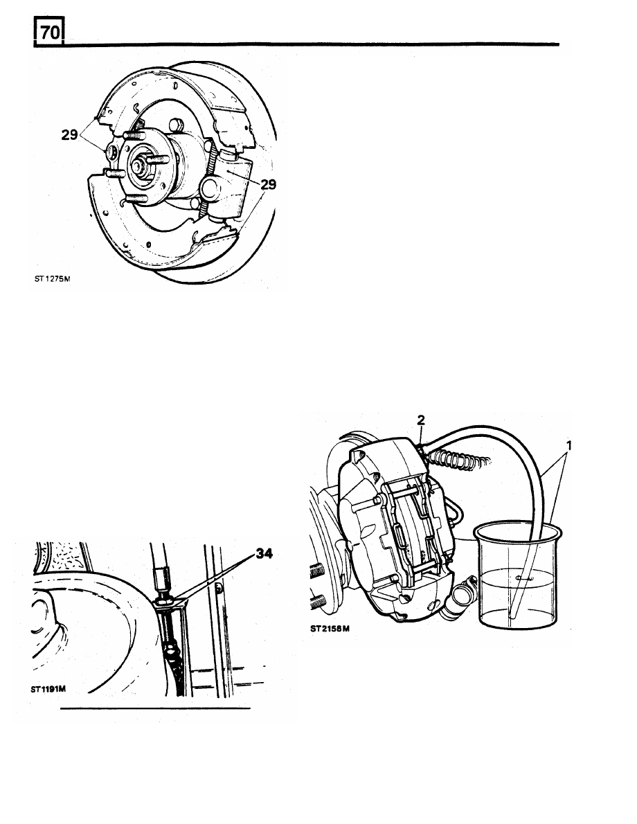
29. Fit new pull-off springs to relined brake shoes
BRAKING
SYSTEM
BLEEDING
THE
BRAKES
Primed
System
Bleed the front brakes first starting with the wheel
nearest to the master cylinder.
1.
Attach a rubber tube to the bleed screw and
immerse the other end in a glass jar
containing
a
quantity
of
clean,
new
recommended brake fluid.
2.
Check that the fluid reservoir is full
to
the
maximum mark.
3. Unscrew the bleed screw approximately
half-a-turn, enough to allow fluid to be
pumped out.
Do
not open the screw too far or
air will be drawn back into the system around
the threads.
4. Smartly depress the foot pedal, pause and
30.
Fit
the brake drum and secure with the
two
then allow the pedal to rapidly return, pause
screws.
again before repeating the procedure.
31.
Connect the expander drawlink to the
5.
Continue with the above sequence until all air
actuating lever with a new clevis pin, washer
bubbles cease whilst ensuring that the
and split pin.
reservoir is kept topped-up.
32. Turn the adjuster cone fully in and tighten the
6. Close the bleed screw immediately after the
two
retaining bolts left slack in instruction 27.
last down stroke, whilst the pedal
is
33. Slacken off the adjuster two 'clicks' and firmly
depressed.
apply the hand lever to centralise the shoes.
The drum should then rotate freely after
releasing the hand lever.
34. Adjust the handbrake cable
to
give the pawl
two
'clicks'
free
movement on the ratchet
before the third 'click' fully expands the shoes
against the drum.
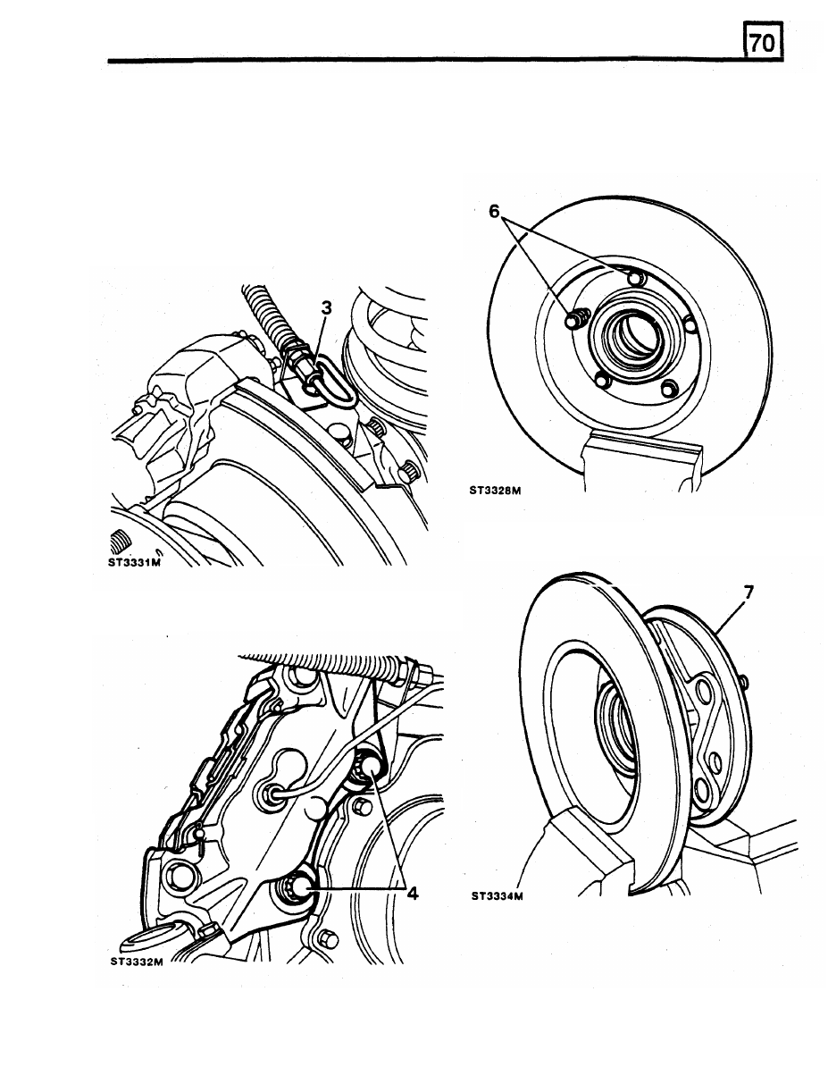
35. Connect the propeller shaft and evenly tighten
the retaining nuts to the correct torque.
36. Remove chocks
from
wheels and connect the
battery.
Unprimed System
To bleed a replacement master cylinder or a fully
drained system.
7.
Top up the fluid reservoir to the maximum
mark.
8.
Open a bleed screw in both circuits and allow
fluid to prime both circuits of the master
cylinder by gravity for approximately five
minutes, then bleed as for a primed system.
4.
Remove the two bolts securing brake caliper
to
the swivel housing and withdraw the
caliper
.
BRAKING
SYSTEM
RENEWING FRONT BRAKE DISCS
5.
Remove the front hub complete with brake
disc by following instructions 6 to
14
in
Removing
SECTION
54 for
front hub
overhaul.
6. Remove the five bolts
to
separate the disc
1.
Disconnect the battery.
from the hub.
2.
Jack-up vehicle, lower on to axle stands and
remove road wheels.
3.
Disconnect the brake pipe union from the
jump hose at the swivel housing bracket.
Cover pipe to prevent entry
of
dirt.
7.
The hub
will
require tapping with
a
mallet
to
finally release it from the disc.
Нет комментариевНе стесняйтесь поделиться с нами вашим ценным мнением.
Текст