Defender (1993+). Manual — part 81
BRAKING SYSTEM
REMOVE AND OVERHAUL BRAKE CALIPERS
Special tool:
18G672 - LRT-70-500 - Piston clamp
Remove caliper
1.
Slacken the wheel retaining nuts, jack-up the
vehicle, lower onto axle stands and remove
the wheels.
2.
Expose the brake flexible hose by moving the
coiled protective covering and clamp the hose.
Disconnect the hose from the caliper.
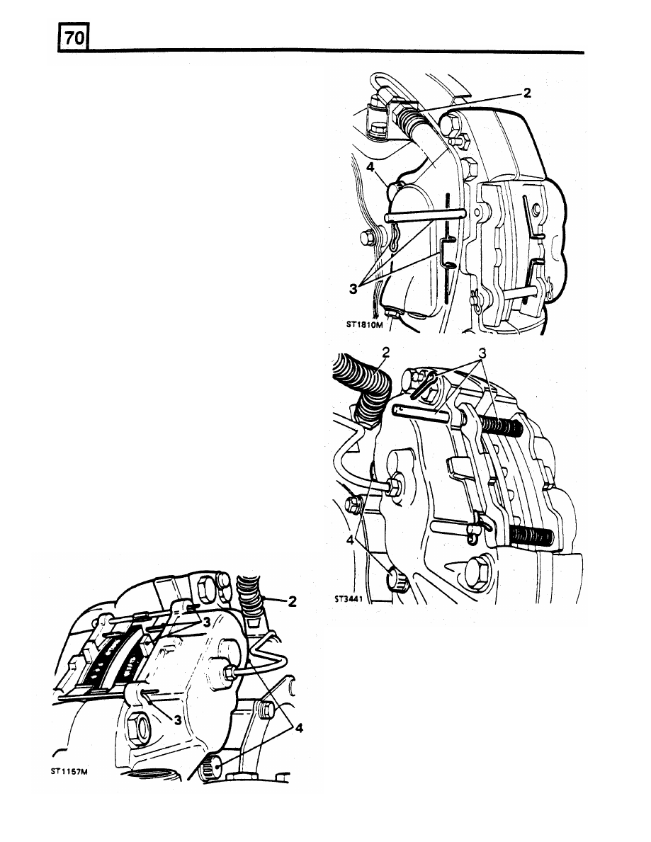
NOTE: Three different methods of retaining the
brake pads are used. Each type is listed
below
and shown
in
the illustrations referred to:
Type A
-
Plate anti-rattle springs
-
Fig. ST1157M.
Type
B
-
Wire anti-rattle springs
-
Fig. ST1810M.
Type C
-
Coil anti-rattle springs
-
Fig. ST3441
3. Removing
friction
pads
-
plate
type
anti-rattle springs
Straighten the splayed ends
of
the pad
retaining pins and withdraw the pins. Collect
the anti-rattle springs and withdraw the pads.
If
the same pads are to
be
refitted, identify
them for assembly
to
their original locations.
Removing friction
pads
-
wire
or
coil
anti-rattle springs
Remove the
four
spring clips or split cotters
and remove the retaining pins. Withdraw me
friction pads. If the same pads are to be
refitted, identify them
for
assembly to their
original locations.
4.
Remove the
two
bolts
and withdraw the
caliper from the vehicle.
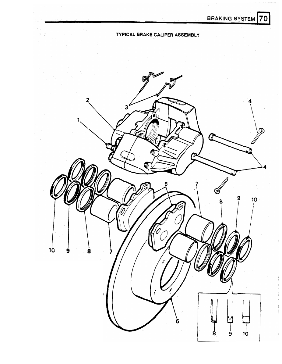
KEY TO
CALIPER
1. Bleed screw
2
Caliper
3. Hold down springs.
4.
Retaining pins and clips
5. Friction pads.
6. Brake disc.
7. Piston.
8. Wiper seal retainer.
9. Wiper seal.
or split pins.
10. Fluid seal.
ST2721M
BRAKING SYSTEM
Slide the assembly, seal first, over the
Do not separate the caliper halves.
protruding piston and into the bore recess
Remove the piston clamp from the mounting
half and use the clamp to press home
the
seal retainer and piston.
5.
Clean the outer surfaces of the caliper with
methylated spirit.
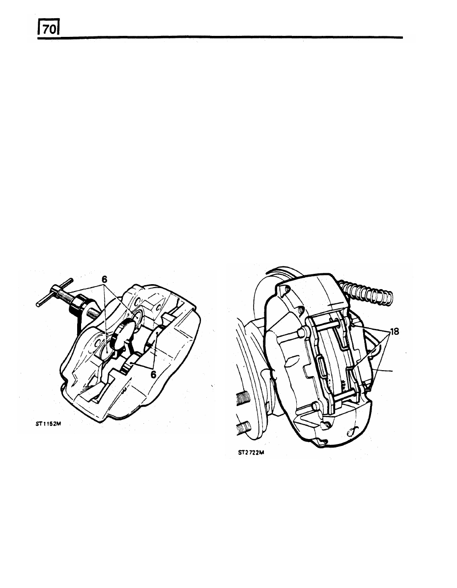
6.
Using special tool
18G672,
clamp the pistons
in the mounting half of the caliper and gently,
keeping fingers clear, and with CAUTION,
Mounting-half pistons
apply air pressure
to
the fluid inlet port to
expel the rim half pistons. Since
it
is unlikely
that both pistons will expel at the same time,
regulate the rate with a suitable piece of
to
13.
timber between the appropriate piston and
caliper.
7 .
Finally, remove the pistons keeping them
15.
Fit the caliper to the axle and secure with the
identified with their respective bores.
two
bolts tightening evenly to the correct
8.
Remove the wiper seal retainer by inserting a
torque,
see
data.
blunt screw driver between the retainer and
16.
Connect the brake flexible hose to the caliper
the seal and prise the retainer carefully from
and remove the hose clamp.
the mouth of the bore.
17.
Lightly Smear the back and edges
of
the pads
9.
Taking care not to damage the seal grooves,
with
disc brake lubricant carefully avoiding the
extract the wiper seal and fluid seal.
friction material.
10.
Clean the bores, pistons and particularly the
18.
Fit the
friction
pads and secure using new
seal grooves
with
clean brake fluid or
pins and split pins and anti-rattle springs.
methylated spirit only. If the caliper or pistons
Splay the ends
of
the early type retaining
are corroded
or
if
their condition is not
perfect
pins.
the parts
must
be
renewed.
14.
Clamp the rim-half pistons and carry out the
same procedure as for removing and fitting
the rim half pistons and seals, instructions
6
Fit calipers and pads to vehicle
Assemble
rim-half
pistons
1 1 .
Coat a
new
fluid seal with Lockheed disc
brake lubricant. Ease the seal into the groove
in the bore using only the fingers and ensure
that
it
is properly seated. The fluid seal and
the groove are not the same in section
so
that
when
the seal is seated
it
feels proud to the
touch at the edge furthest away
from
the
mouth
of
me bore.
12.
Smear the appropriate piston with hydraulic
brake lubricant and insert
it
squarely into the
bore by hand only.
Do
not
tilt
the
piston
during insertion and leave approximately
-
mm
projecting from the bore.
13.
Coat a new wiper seal with hydraulic brake
lubricant and fit it to a new seal retainer.
19. Bleed the brake hydraulic system as
described later
in
this section.
28.
When the
foregoing
instructions have been
completed on both calipers, depress the brake
pedal
firmly
several times to locate the friction
pads.
21.
Fit the road wheels, remove the axle stands
and finally tighten the road wheel nuts, see
data.
22.
Road test the vehicle. remembering
that if
new
friction
pads have been
fitted
they are not
‘bedded
- in' and may take several hundred
miles before the brakes are at maximum
efficiency.
BRAKING
SYSTEM
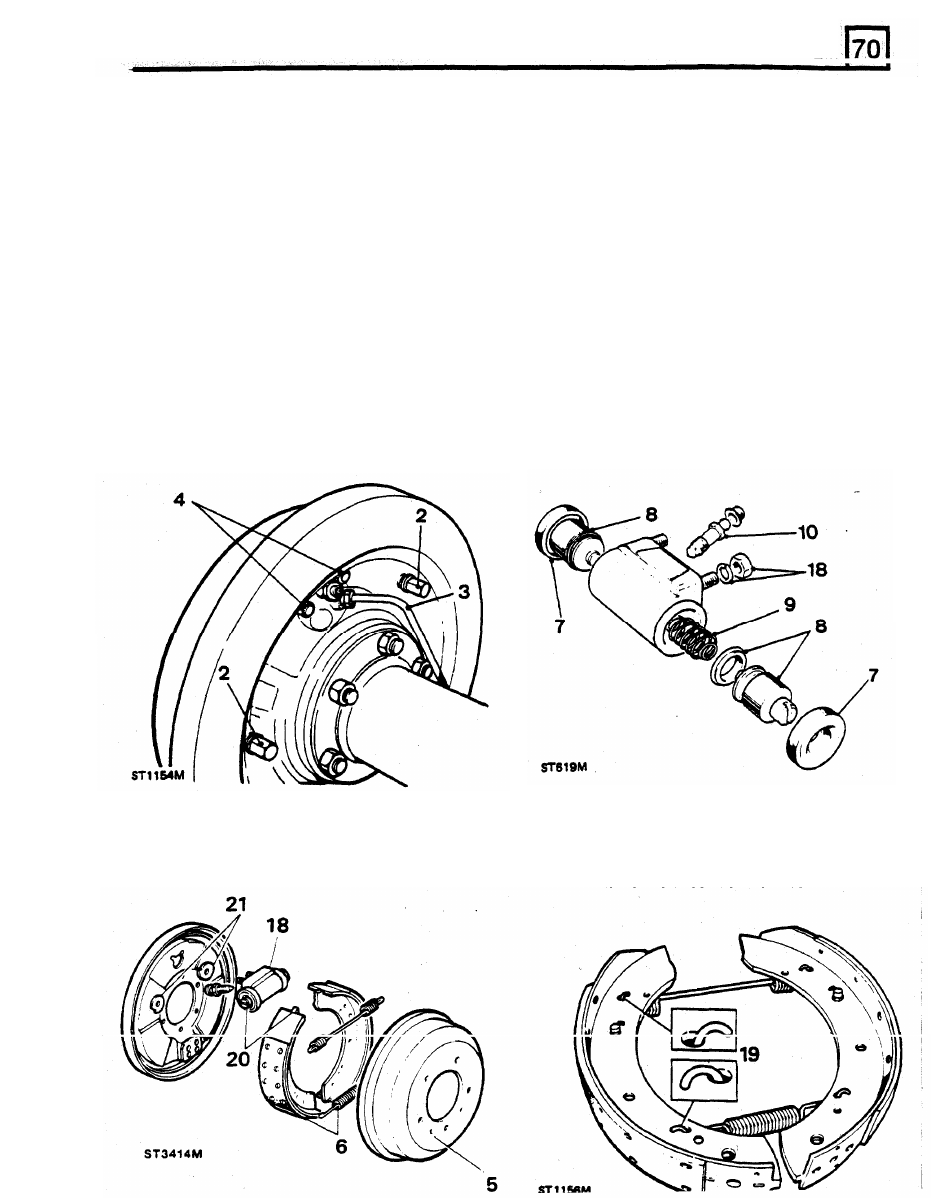
OVERHAUL REAR BRAKES - 110 models
DISMANTLING
7 . Remove the two dust covers.
WARNING:
Do
not use an air line to blow
dust
from the brake assemblies - asbestos dust from
brake linings can be a serious health
risk
if
11.
Clean components with Girling cleaning fluid
inhaled.
and allow to dry.
12.
Examine the cylinder
and pistons for
1.
Slacken the road wheel nuts, jack-up the
corrosion, scores and wear. Renew any
component that is not satisfactory or replace
complete cylinder assembly.
2.
Slacken the two brake shoe adjusters on the
13.
Fit new seals to the pistons noting that the
brake drum.
14. Lubricate the pistons with new clean Girling
3. Disconnect the brake fluid pipe to the wheel
ingress of dirt.
16. Fit the dust covers.
4. Remove the two retaining nuts and withdraw
the wheel cylinder
from
the back-plate.
Dismantle and overhaul wheel cylinder
8.
Withdraw the pistons and discard seals.
9.
Remove the spring.
10.
Remove the bleed screw.
vehicle, lower onto axle stands and remove
the road wheels.
rear of the back-plate to assist removal of
seal lip is towards the cylinder.
brake fluid.
cylinder and cover the pipe end to prevent
15.
17. Fit the bleed screw and tighten to 0,5 to
0,8
kgf
m.
Fit the spring between the
two
pistons.
Assembling rear brake
5. Remove the single retaining screw and
18.
Fit the wheel cylinder to the back-plate and
6
*
Assemble new brake shoe pull-off springs to
secure with the two nuts and spring washers.
relined brake s h o e s as illustrated.
withdraw the brake drum.
position of the pull-off springs.
Lever off the brake shoes whilst noting the
19.
Нет комментариевНе стесняйтесь поделиться с нами вашим ценным мнением.
Текст