Defender (1993+). Manual — part 99
ELECTRICAL EQUIPMENT
TEST 7 :
Visual and
HT Cable Checks
Examine:
Should be:
1.
Distributor Cover
Clean, dry, no tracking
2.
Coil Top
Clean, dry, no tracking
3.
HT Cable Insulation
Must not be cracked
4.
HT Cable Continuity
Must not be open
5.
Sparking Plugs
Clean, dry, and set to
marks
marks
chafed
or
perished
circuit
correct gap.
NOTE:
1.
Reluctor
Must not foul pick-up
2.
Rotor and Flash
Must
not be cracked
or leads
or
show signs
of
tracking marks.
8
REISSUED:
FEB
1993
ELECTRICAL EQUIPMENT
ALTERNATOR - TYPE A127
BATTERY
Remove and refit
Removal
WARNING: During battery removal or before
carrying out any repairs or maintenance to
1.
Disconnect battery ground lead.
electrical components always disconnect the
2 .
Disconnect the electrical leads from the
battery negative lead first. If the positive lead is
alternator.
disconnected with the negative lead in place,
3.
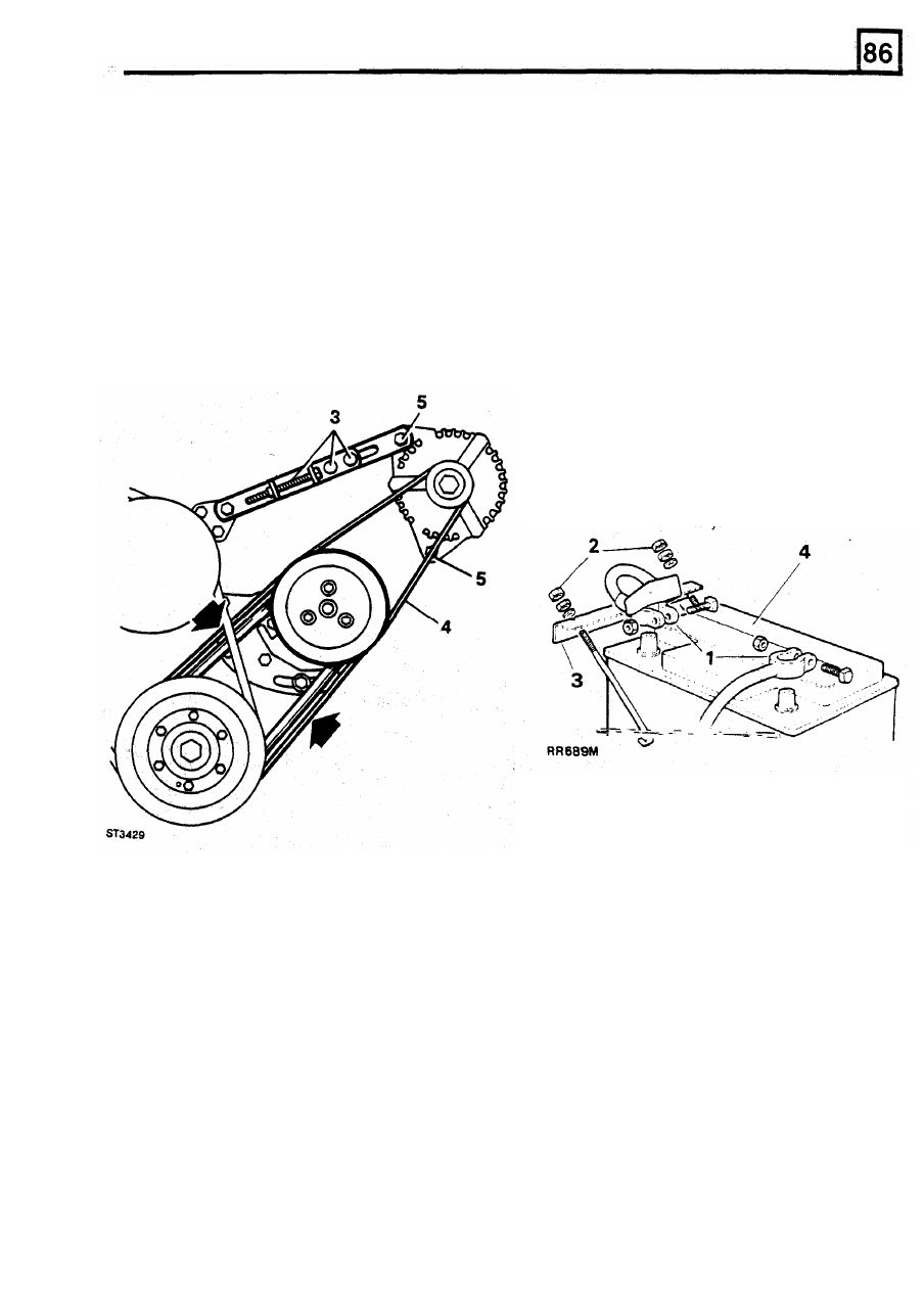
Slacken the two tensioner nuts and rotate the
accidental contact of the wrench to any
tensioner screw anti-clockwise to slacken the
grounded metal part could cause a severe spark,
belt tension.
possibly resulting in personal injury. Upon
4.
Remove the belt.
installation of the battery the positive lead
5.
Remove the two securing bolts and withdraw
the alternator from the engine.
Remove and refit
should
be
connected first.
Removing
1.
Disconnect battery ground lead followed by
2. Release the four nuts securing the battery
3.
Remove the bracket from the studs.
4. Remove the battery
the disconnection of the positive lead.
bracket in position.
Refitting
5.
Reverse the removal procedure.
Refit
NOTE: Coat the battery clamps
and
terminals
with petroleum jelly before
refitting.
6. Position n the alternator on
the
engine and fit
7 .
Adjust
the
drive
belt
tension,
see
8.
Connect the electrical leads
to
the alternator
the securing bolts.
MAINTENANCE.
and connect the battery.
REISSUED:
FEB
1993
9
ELECTRICAL EQUIPMENT
STARTER
MOTOR - Type
M78R
Overhaul
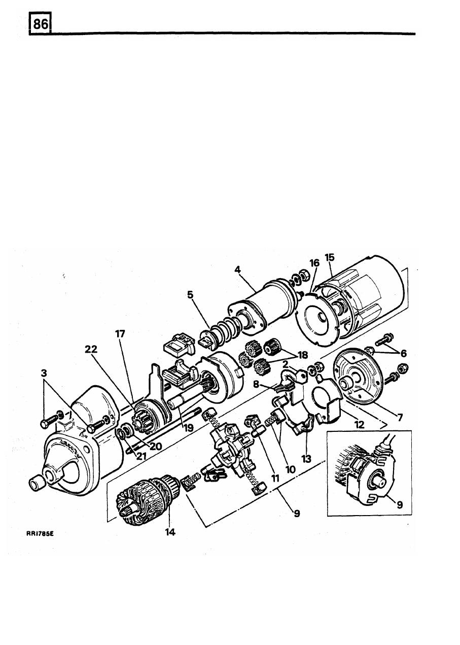
Dismantling
1.
Remove the starter motor.
13. Withdraw the brushes and bus bar.
2. Remove the braid between the starter and the
solenoid terminal.
15.
Remove the yoke.
3. Remove the solenoid fixing screws.
16. Remove the intermediate bracket.
4.
Withdraw the solenoid body.
17. Loosen and remove the through bolts from the
5.
Lift and remove the solenoid plunger.
drive end bracket.
6.
Remove two nuts and two screws from the
commutator end bracket.
7.
Remove the commutator end bracket.
8. Remove the grommet from the yoke.
9.
Lift the brushbox assembly clear of the
jump ring back towards the drive.
armature.
21.
Prise the jump ring from its locating groove.
14. Remove the armature from the yoke.
18. Remove the sun and planet gears.
19. Push out the drive shaft sprocket assembly
from the drive end bracket.
20.
Carefully tap the thrust collar
from
over the
10. Remove the brush springs.
22.
Remove the drive assembly from the drive
11. Unclip and remove the earth brushes.
shaft.
12.
Remove the insulating plate.
10
REISSUED: FEB 1993
ELECTRICAL EQUIPMENT
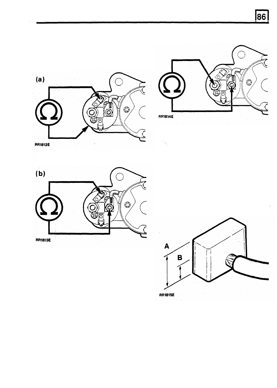
Inspecting
Solenoid
Solenoid plunger removed, ohmmeter should read
infinity.
23. Check the continuity and resistance value
of
windings by connecting an ohmmeter as
shown.
Solenoid plunger operated by hand, ohmmeter
should read zero.
If
test results are unsatisfactory, replace the
solenoid.
If
results are correct proceed to 25.
(a) Resistance value should be: 1.074 ± 0.035
ohms
25. Check operation of spring for freedom of
movement.
Brush gear
26. Check brush springs and ensure that the
brushes move freely in their holders.
Clean the brushes with a petrol moistened cloth, if
required.
(b) Resistance value should be: 0.298
±
0.015
ohms
If
test results are unsatisfactory replace the solenoid.
If
results are correct proceed to 24.
24. Check the contacts by
connecting an
ohmmeter as shown.
Brush length new, Dimension A is 9 mm.
Minimum brush length, Dimension B is 3.5
mm.
REISSUED: FEB
1993
11
Нет комментариевНе стесняйтесь поделиться с нами вашим ценным мнением.
Текст