Defender (1993+). Manual — part 25
ENGINE
6.
Heat water and observe temperature at which
thermostat opens.
4.
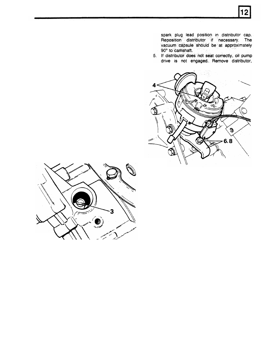
Fit distributor
to
engine, check that centre line
of
rotor arm is now in line with number one
8. Clean
intake and
manifold and thermostat housing
9. Fit thermostat with jiggle pin uppermost.
NOTE:
Airlocks
may
develop
in cooling
positioned,
with
consequent
loss
of
coolant and possible overheating.
10.
Fit housing with new gasket, tighten two bolts
to
correct torque, 28 Nm.
system
if
thermostat
is
incorrectly
reset oil pump drive tongue, repeat operation.
FIT
DISTRIBUTOR
1.
Turn crankshaft
to
bring number one piston
to
6°
BTDC on compression stroke (both valves
closed number one cylinder).
2. Turn distributor drive until rotor arm is
approximately
30"
anti-clockwise from number
one spark plug lead position on cap.
3. Turn oil pump and distributor drive shaft until
tongue is in approximate position illustrated.
RR178E
6.
Fit clamp and nut, leave loose.
7.
Rotate distributor until peak on pick-up lines
up with a peak on reluctor ring. Remove rotor
arm for better view.
CAUTION: On no account must engine be
started before this operation is carried out.
8. Secure distributor in this position by tightening
clamp nut.
ST859M
7. Disard thermostat if faulty.
mating faces.
ENGINE
RR1876E
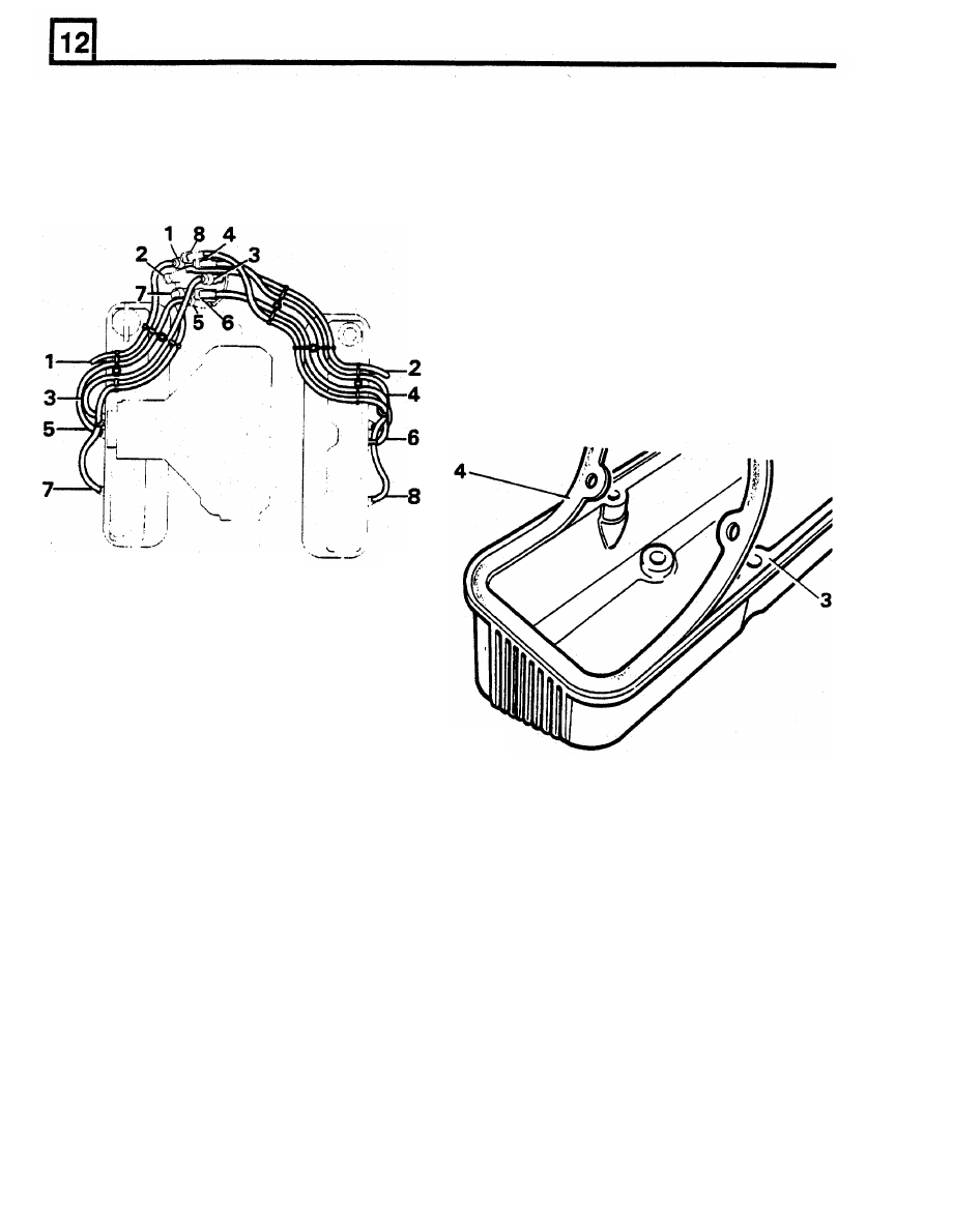
9.
Fit
distributor cap and spark plugs. Connect
H.T.
leads as shown in illustration RR1876E.
NOTE: This distributor setting is to enable
1.
An oil baffle is
fitted
inside each rocker cover,
engine to
be started. When engine is
Remove
two
screws to remove baffle for
refitted the ignition timing must
be set
cleaning.
using electronic equipment.
2.
Remove old gasket and sealant from covers
and cylinder heads. Clean and
dry gasket
mounting face, using Bostik cleaner
6001.
Apply Bostik
1775
to seal face and gasket,
use a brush
to
ensure an even film. Allow
adhesive
to
become touch-dry, approximately
fifteen minutes.
NOTE: The gasket fits one way only,
it
must
be
fitted accurately first time.
Subsequent
movement would destroy
bond.
FIT ROCKER COVERS
ST853M
3.
Fit pilot studs in rocker cover fixing holes to
guide gasket onto cover and into recess.
Press gasket into place ensuring that outer
edge firmly contacts recess wall.
4.
Allow covers to stand for thirty minutes before
fitting.
5. Secure rocker covers to cylinder heads with
short screws inboard, long screws outboard.
Tighten
to correct torque, 9
Nm.
ENGINE
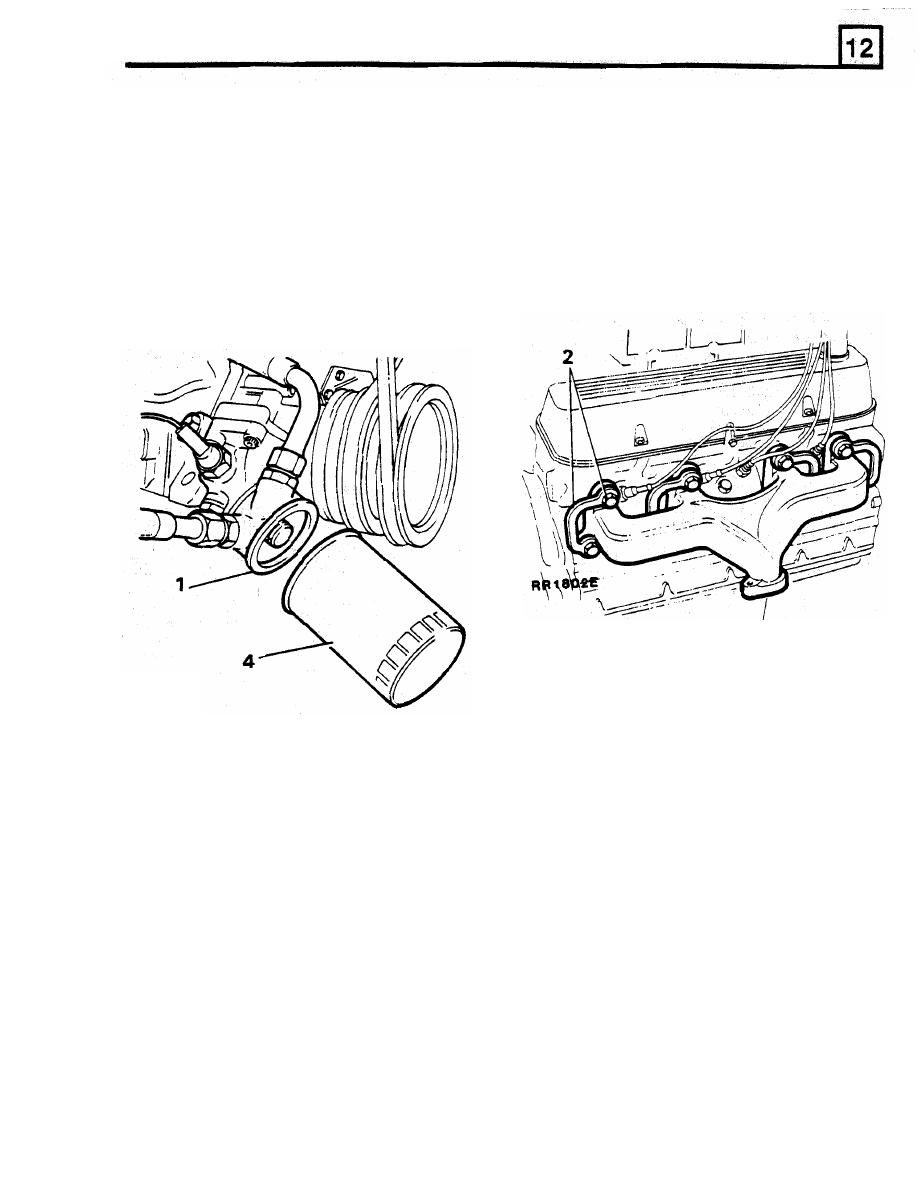
FIT ENGINE
OIL FILTER
FIT EXHAUST MANIFOLD
1.
Clean oil cooler adaptor mating face.
1.
Ensure mating surfaces of head and exhaust
2.
Coat sealing ring of new filter with clean
manifold are clean. Fit new gaskets
to
engine oil.
exhaust manifold. Coat threads of bolts with
3.
Fill filter with new oil as far as possible, noting
anti-seize compound.
angle at which filter is
to
be fitted.
2.
Position manifold on cylinder head and
fit
new
4.
Screw on filter until sealing ring touches
lockplates, securing
bolts
and plain washers.
mating face, then tighten a further half turn by
The plain washers are fitted
between manifold
hand only.
DO NOT OVERTIGHTEN.
and lockplates. Evenly tighten manifold bolts
5. Refill engine with specified grade and quantity
to correct torque. 20 Nm. Bend over lock tabs.
of oil.
MISCELLANEOUS AND NON-STANDARD ITEMS
Fit remaining items of equipment, miscellaneous
hoses, pipes, filters, clips and brackets in position.
RR2618S
ENGINE
CYLINDER HEAD GASKETS
-
RENEW
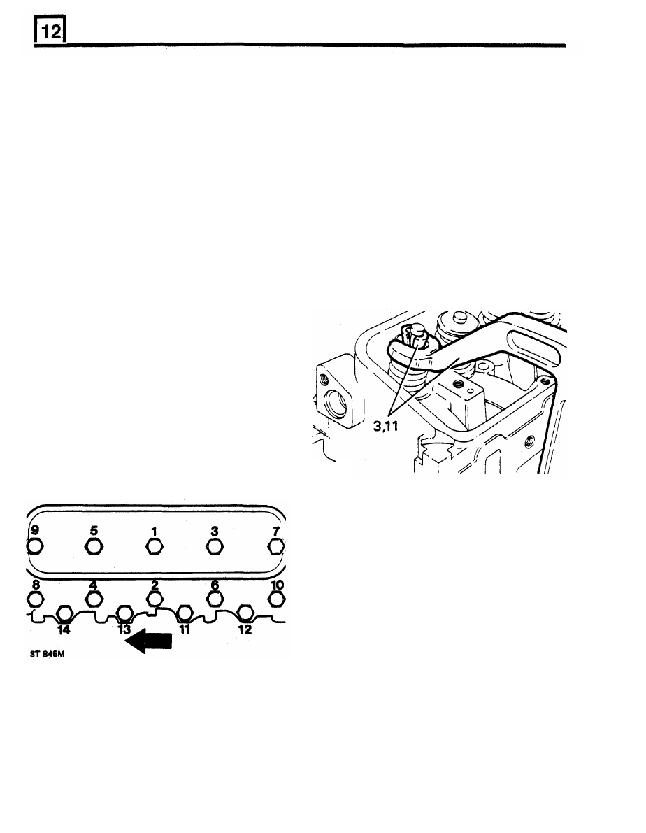
23. Tighten bolts progressively in sequence, see
illustration number ST845M. Finally tighten
to
1. Drain cooling system.
torque:
2. Remove inlet manifold.
Outer row 60 Nm
3. Remove alternator.
Centre row
90
Nm
4. Remove rocker shafts.
Inner row
90
Nm.
5.
Remove push rods.
24. When all bolts have been tightened, re-check
6. Remove power steering pump belt.
for correct torque.
7. Remove alternator bracket.
25. Reverse instructions 12
to
1.
8. Remove both exhaust manifolds.
9.
Remove air cleaner assembly.
CYLINDER HEADS
-
RENEW
10. Remove air flow meter.
11. Remove earth leads from rear
of
left hand
1.
Remove cylinder heads and gaskets.
cylinder head
2. Remove spark plugs.
12. Right hand cylinder head
-
remove breather
3. Using spring compressor 18G 106A, remove
pipe from lifting bracket.
13. Loosen
cylinder
head
bolts,
reversing
tightening sequence.
14. Remove cylinder heads.
15.
Remove cylinder head gaskets.
16. Clean exhaust mating faces.
17. Clean head and block faces.
18. Fit new cylinder head gaskets, word TOP
uppermost.
DO NOT use sealant.
19.
Oil cylinder bores.
20.
Clean threads of head bolts and coat with
Loctite 572.
21. Locate cylinder heads on block.
22. Locate cylinder head bolts
in position
illustrated.
Long bolts
-
1, 3, and 5.
Medium
bolts
-
2,
4,
6, 7, 8,
9
and 10
Short bolts
-
11,
12,
13,
and 14
valves, collets, springs and caps.
RR3819M
4.
From left hand cylinder head, remove earth
lead studs.
5. Remove PAS pump pivot stud.
6. Right hand cylinder head, remove rear lifting
bracket.
7. Fit lifting bracket to new right hand cylinder
head.
8.
Fit
PAS pump pivot stud, earth lead studs
to
new left hand cylinder head.
9. Regrind valves.
10. Lubricate valve stems,
fit
valves, springs, and
caps. Fit new seals
to
inlet valve stems only.
11. Using
spring
compressor
18G
106A,
compress springs,
fit
collets. Tap valve to
check correct collet seating.
10. Fit spark plugs.
11. Fit cylinder heads with new gaskets.
NOTE: Left hand cylinder head illustrated,
arrow points to front of
vehicle.
Нет комментариевНе стесняйтесь поделиться с нами вашим ценным мнением.
Текст