Defender (1993+). Manual — part 75
STEERING
Torque peak check
NOTE:
That the addition or subtraction of
a
0,07
The purpose of this check is
to
determine the point
mm shim will move the torque peak area by
at
which the rolling resistance is the greatest when
approximately one quarter of a turn of the input
the steering is turned from lock to lock. This
shaft.
resistance, which must be equally distributed, should
be when the sector shaft roller is positioned along
Shim washers are available from Land Rover
the centre portion of the worm approximately two
Parts and Equipment
in
the following sizes: 0,03
revolutions of the input shaft from either the left
or
mm, 0,07 mm, 0,12 mm and 0,24 mm.
right hand lock.
3. Having added or subtracted shims as
The correct position of the resistance depends upon
necessary, reassemble the steering box and
the amount of shimming behind the input shaft inner
check that the torque peak position
IS
now
bearing cup. Provided that the original shim pack
correct.
has been refitted, the torque peak position should be
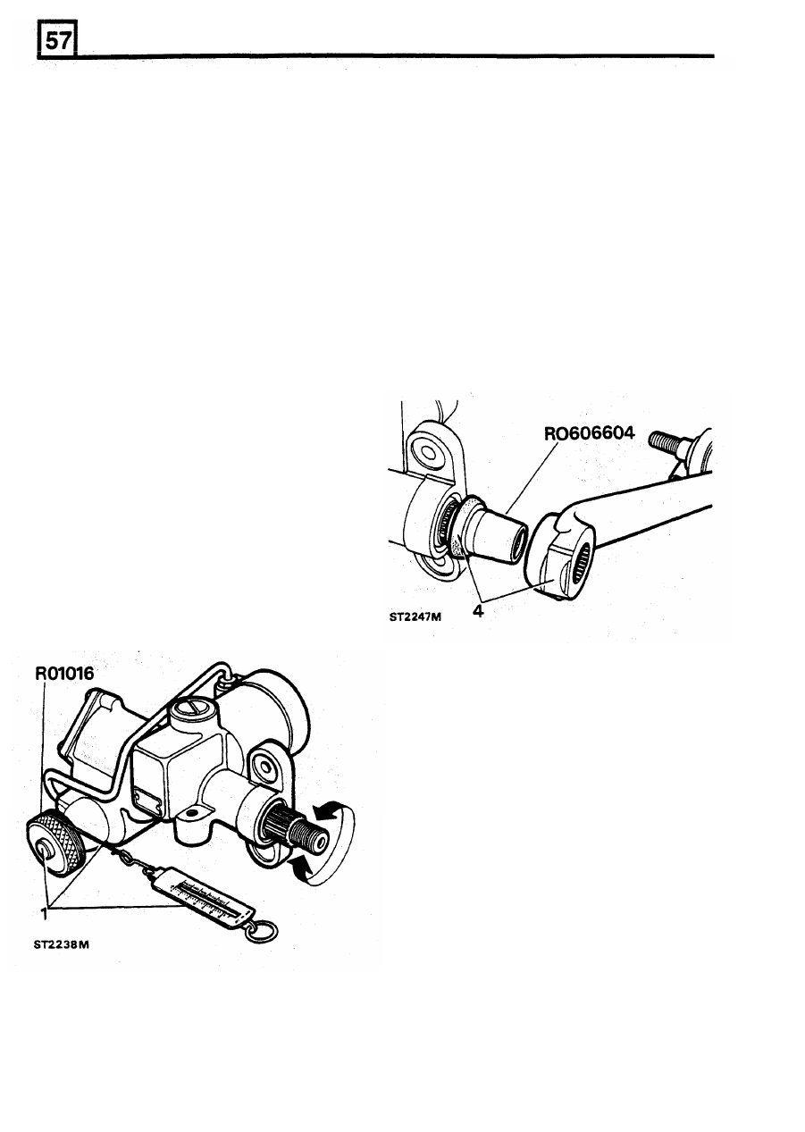
4.
Using seal saver
RO
606604, fit
a new outer
correct unless major components have been
dust seal over the sector shaft. Fit the drop
renewed. The procedure for checking and adjusting
arm
to
the sector shaft and a new lock
the torque peak is contained in the following
washer. Fit and tighten the retaining nut to the
instructions.
correct torque and bend the lock tab over a
flat of the nut.
1.
Attach the torque setting tool RO 1016 to the
input shaft and turn it fully anti-clockwise.
Wind cord round the tool and fasten a spring
balance to the free end
as
before. Turn the
input shaft by pulling the spring balance and
note the position where the highest figure is
obtained. If the highest figures are not
recorded along the middle portion of the travel
as explained above adjustment is necessary.
2.
Adjustment involves the dismantling of the
steering box and removal of the input shaft
inner bearing cup and shims. If the torque
peak (highest figure) occured before the
centre position, add shims
to
the pack.
Remove shims if the torque peak occurs after
the centre Position.
Fitting steering box to vehicle and testing
1.
Fit the steering box to the vehicle and
replenish the system with the correct make
and grade of fluid, For this information refer to
'RECOMMENDED
LUBRICANTS
AND
FLUIDS’
and bleeding the power steering
system.
2.
To
test the effectiveness
of
the
steering box
overhaul and the system
for
leaks, run the
engine and hold the steering hard on full lock
in both directions whilst a second person
checks for fluid leaks.
CAUTION:
Do not hold
the
steering on full lock
for more than thirty seconds in any one minute
t o avoid overheating the fluid and possibly
damaging the seals.
3. Finally road test the vehicle.
20
REISSUED: FEB 1993
STEERING
POWER
STEERING
SYSTEM
-
Adwest
Test
Lightweight box
If
there is
a
lack of power assistance for the steering
Bleed
the pressure of the hydraulic pump should be
checked first before renewing any components of the
system. The fault diagnosis chart should also be
1.
Fill the steering fluid reservoir
to
the mark on
the side of the reservoir with one of the
used to assist in tracing faults
in
the power steering.
recommended fluids.
2.
Start and run the engine until it attains normal
operating temperature.
3.
Check
and
correct the reservoir fluid level.
Procedure
1.
The hydraulic pressure test gauge is used for
testing the power steering system. This gauge
NOTE: During the carrying out
of
items
4,
5
and
is calibrated to read up
to
140 kgf/cm² and the
6, ensure that the steering reservoir is kept full.
normal pressure which may be expected
in
Do
not increase the engine
speed or move the
the power steering system
is
77
kgflcm².
steering wheel.
2. Under certain fault conditions of the hydraulic
pump it
is
possible to obtain pressures up to
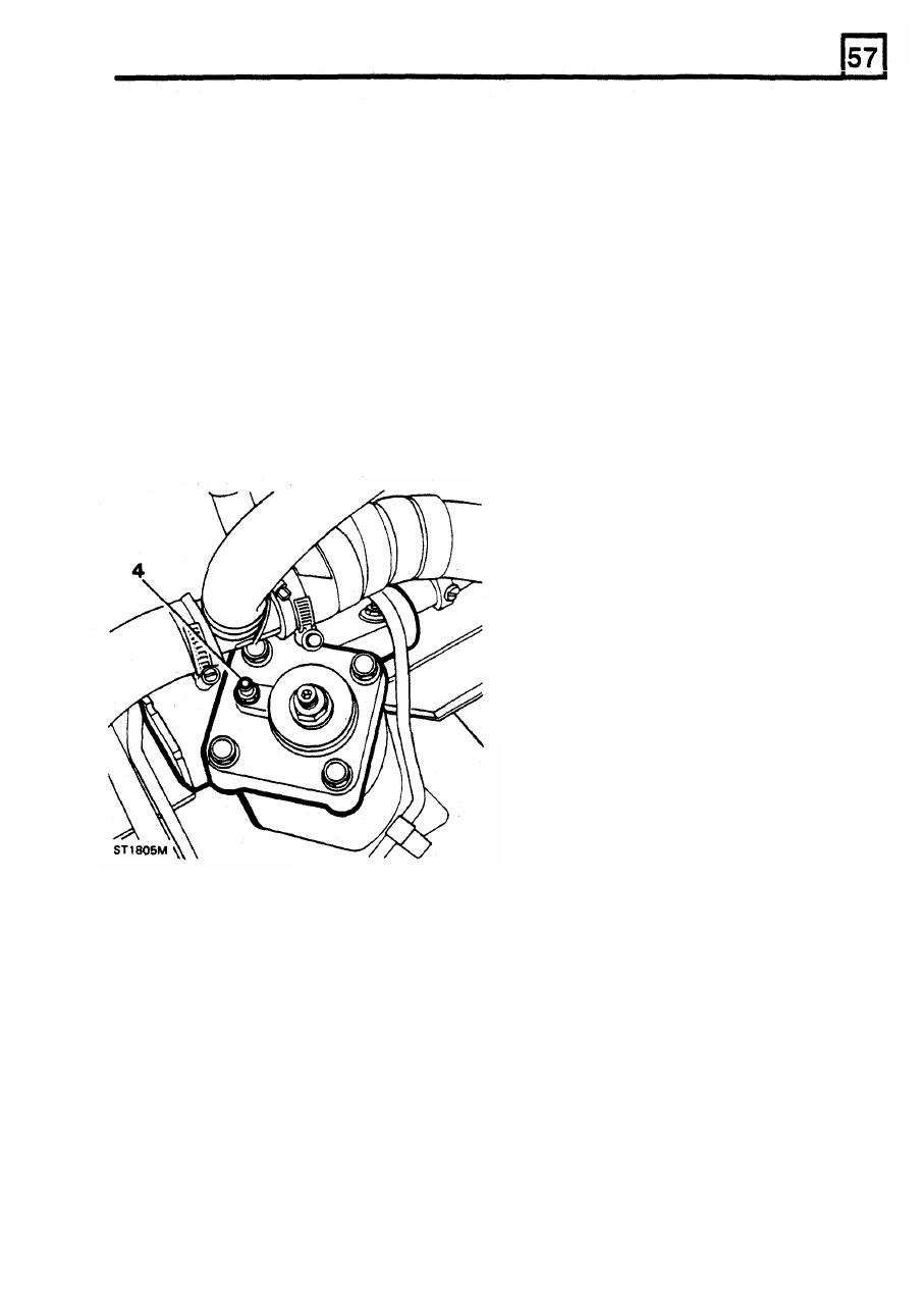
4. Run the engine at idle speed, slacken the
105
kgf/cm². Therefore,
it
is
important to
realise that the pressure upon the gauge is
in
direct proportion to the pressure being exerted
upon the steering wheel. When testing, apply
pressure to the steering wheel very gradually
while carefully observing the pressure gauge.
3.
Check, and if necessary replenish, the fluid
reservoir.
4. Examine the power steering units and
connections for leaks.
All
leaks must be
rectified before attempting to test the system.
5.
Check the steering pump drive belt for
condition and tension, rectify as necessary.
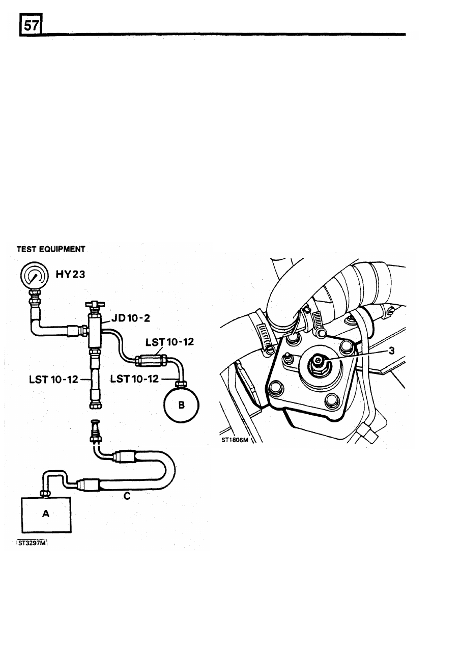
6. Assemble the test equipment and fit to the
vehicle as illustrated.
7.
Open the tap in the adaptor.
8.
Bleed the system but exercise extreme care
when carrying out this operation
so
as not to
overload the pressure gauge.
9.
With the system in good condition, the
pressures should be as follows:
a. Steering
wheel
held hard on full lock and
engine running at 1,000 rev/min, the pressure
should be 70
to
77
kgf/cm².
b. With the engine idling and the steering
wheel held hard on full lock, the pressure
should be
28
kgf/cm² minimum.
These checks should be carried out first on one lock,
then on the other.
CAUTION: Under no circumstances must the
steering wheel be held on full lock for more than
30
seconds in any one minute, otherwise there
will
be a tendency for the oil to overheat and
possible damage to the seals may result.
bleed screw. When fluid seepage past the
bleed screw is observed, retighten the screw.
5.
Ensure that the fluid level is in alignment with
the mark on the reservoir dipstick.
6.
Wipe
off
all fluid released during bleeding.
7. Check all hose joints, pump and steering box
for fluid leaks under pressure by holding the
steering hard on
full
lock in both directions.
CAUTION: Do not maintain this pressure
for
more than
30
seconds in any one minute, to
avoid causing the oil to overheat and possible
damage to the seals, The steering should
be
smooth lock-to-lock in both directions, that is, no
heavy or light spots when changing direction
when the vehicle is stationary.
10.
Release the steering wheel and allow the
engine
to
idle. The pressure should be below
7
kgflcm².
8.
Carry out a short road test. If necessary,
repeat the complete foregoing procedure.
REISSUED:
FEB
1993
21
STEERING
11.
If
the pressures recorded during the foregoing
ADJUST POWER STEERING
BOX
-
Adwest
test are outside the specified range, or
Lightweight box
pressure imbalance
I
S
recorded, a fault exists
in the system.
To
determine if the fault is in
NOTE: The condition of adjustment which must
the steering box
or
the pump, close the
be checked
is one
of
minimum backlash without
adaptor tap for a period not exceeding five
overtightness when the wheels are
in the
seconds.
straight-ahead position.
12.
If
the gauge fails to register the specified
pressures, the pump
is
inefficient and the
1.
Jack up the front
of
the vehicle until the
pump relief valve should be examined and
wheels are clear of the ground.
renewed as necessary.
13.
Repeat the foregoing test after renewing the
WARNING: Wheels must
be chocked in
all
relief valve and bleeding the system. If the
circumstances.
pump still fails to achieve the specified
pressures, the pump should be overhauled or
2.
Gently rock the steering wheel about the
a new unit fitted.
straight-ahead position to obtain the 'feel'
of
14.
If
pump delivery is satisfactory and low
the backlash present. This backlash must not
pressure or marked imbalance exists, the fault
be more than 9,5
mm.
must
be
in the steering box valve and worm
3.
Continue the rocking action whilst an assistant
assembly.
slowly tightens the steering box adjuster
screw after slackening the locknut until the rim
movement
is
reduced
to 9,5 mm maximum.
4.
Tighten the locknut, then turn the steering
wheel
from lock
to
lock and check that no
excessive tightness exists at any point.
5.
Lower the vehicle
to
ground level and remove
the wheel chocks.
6. Road test the vehicle.
A.
Steering box
B. Steering pump
C. Existing hose from steering box
22
REISSUED: FEB 1993
STEERING
PIPE CONNECTIONS TO STEERING
BOX
When fitting a new or overhauled steering box
observe the following procedure.
1.
Remove dust caps from ports.
2.
Immediately fit pipes finger tight.
3. Tighten the 16 mm union nut to 20 Nm.
4.
Tighten the 14 mm union nut
to
15
Nm.
STEERING BOX SECTOR SHAFT SEAL - renew
with steering box fitted to vehicle
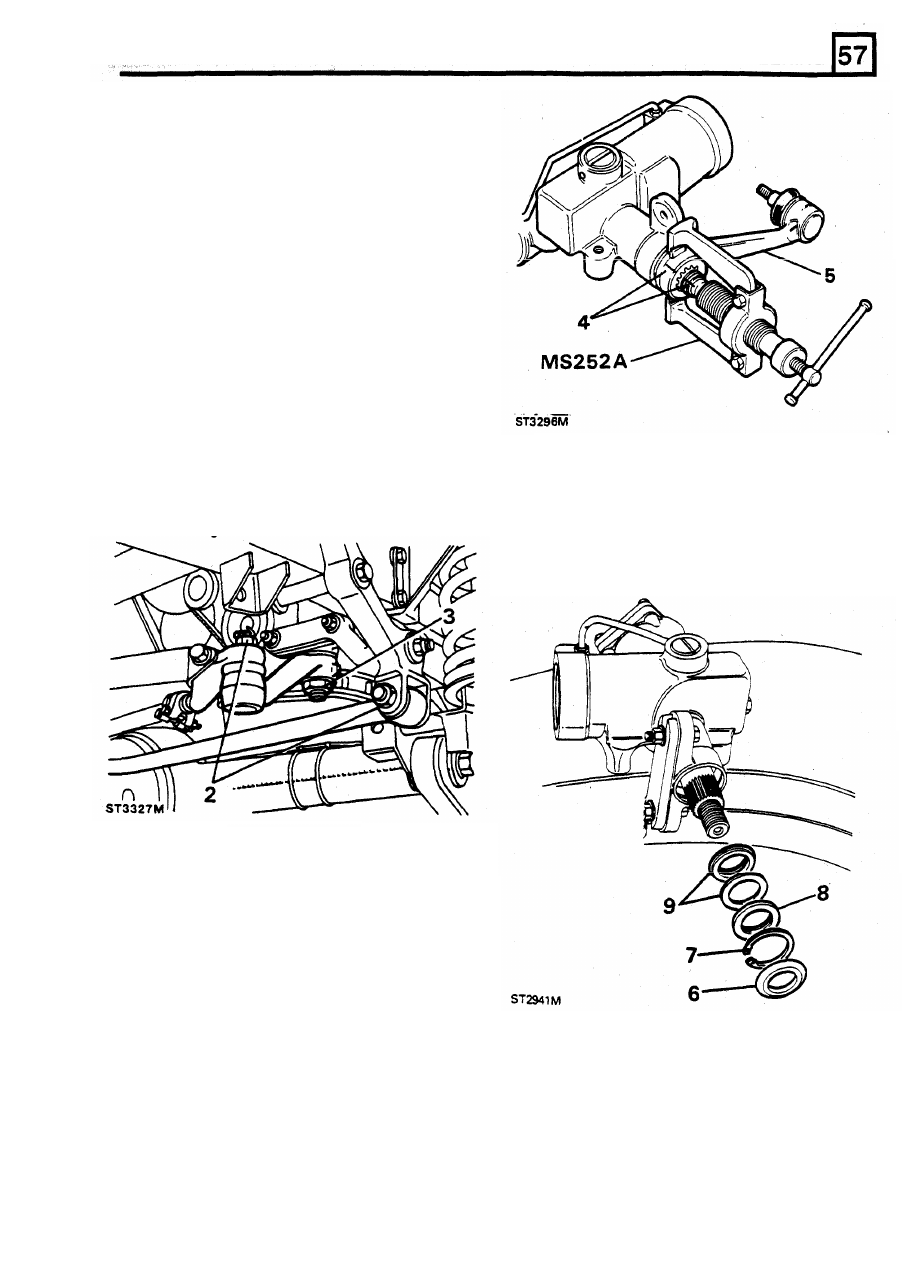
Special tools
Drop arm puller MS 252A / LRT-57-012
Seal replacer LST 125A / LRT-57-010
1.
Working
from
beneath the vehicle set the
steering in approximately the straight ahead
6.
Remove the dust seal, if fitted, and clean the
position.
area around the sector shaft seal.
2.
Release the ball pin from the drag link, and
7.
Remove the circlip.
one end
of
Panard rod.
8.
To
remove the seal pack, drill
two
3 , 0 mm
3. Release the lock tab from the drop arm
holes diametrically opposite into the metal dirt
retaining nut and remove
the
nut
seal. Insert a 4 mm self tapping screw in each
hole then, with pliars pull the seal from the
box.
9.
Remove the extrusion washer and inner seal.
4.
Before removing the drop arm, mark its
relationship to the sector shaft to assist
assembly.
5. Using pulley MS
252A
or a suitable
alternative, withdraw the drop arm.
10.
With
a
suitable
probe,
remove
the
anti-extrusion washer and inner seal.
REISSUED:
FEB
1993
23
Нет комментариевНе стесняйтесь поделиться с нами вашим ценным мнением.
Текст