Defender (1993+). Manual — part 40
LT77S MANUAL
GEARBOX
REMOVE LT77S MANUAL GEARBOX AND
LT230
11.
Release the air filter
hose
at
filter.
TRANSFER BOX
12.
Raise the ramp.
13.
Remove the eight nuts and bolts securing the
WARNING: Where the use
of a transmission
chassis cross member and using a suitable
hoist is necessary,
it
is absolutely essential to
means of spreading the chassis, remove the
follow
the
manufacturers' instructions to ensure
cross member.
safe and effective use of the equipment.
14. Place
a suitable container under the
transmission, remove the three drain plugs,
allow the oil to drain and refit the plugs. Clean
filter on the extension housing plug before
refitting.
15.
Remove the intermediate exhaust pipe and
silencer section as
follows:
(a) Release the connection to the front pipe
at the flange.
(b) Release the connection
to
the rear section
at the flange immediately behind the
silencer.
(c) Remove the
'U' bolt
retaining the pipe to
the bracket attached
to
the transfer box.
16.
Mark the flanges for
reassembly and
disconnect the front propeller shaft from the
transfer box.
17.
Similarly, disconnect the rear propeller shaft.
18.
Disconnect the speedometer cable from the
rear
of the transfer box.
19.
Disconnect the handbrake inner cable by
removing the split pin and clevis pin.
20. Slacken the retaining nuts and release the
handbrake outer cable from the bracket.
21.
Remove the two bolts and withdraw the clutch
slave cylinder from the bell housing.
22.
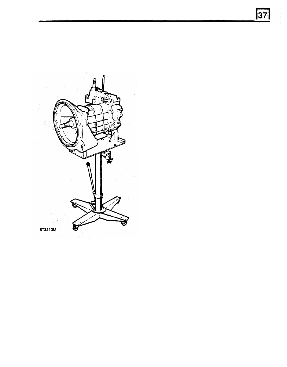
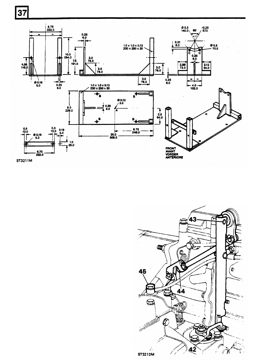
Manufacture a cradle
to
the dimensions given
in the drawing and attach it
to
a transmission
hoist.
To achieve balance of the transmission
unit when mounted on the transmission hoist,
it
is essential that point A is situated over the
centre
of the lifting hoist ram. Drill fixing holes
1.
Install the vehicle on a ramp.
B
to suit hoist table. Secure the transmission
2. Disconnect the battery.
unit to the lifting bracket at point
C,
by means
3. Remove the gear lever knob.
of the lower bolts retaining the transfer
4.
Remove the transfer and differential lock
gearbox rear cover.
knob.
23.
Remove the bottom
two
bolts
from the transfer
5. Remove the gear lever cover.
box rear cover and use them
to
attach the
6. Remove the
10
mm Nyloc nut and plain
rear end of the cradle to the transfer box.
washer. Mark the gear lever spline setting and
Ensure that the tube in the centre
of the
detach the gear lever and gaiter from the
cradle locates over the extension housing
splined lower gear lever.
drain plug.
7.
Select high range to prevent the transfer
24. Raise the hoist just enough to take the weight
gearbox selector lever fouling the tunnel when
of the transmission.
removing the gearbox.
25. Remove the three nuts and bolts securing the
8.
Remove the bonnet.
transfer box LH and
R H mounting brackets
9.
Remove the nuts and bolts retaining the fan
to
the chassis.
Cowl to the engine and move the cowling
26.
Remove the nuts retaining the brackets to
the
forward, clear of the engine.
speedometer cable, and starter motor harness
from clips at rear of the engine.
mounting rubbers and remove the brackets.
10. Release the transmission breather pipes,
27.
Lower the hoist sufficiently to allow the
transfer lever to clear the transmission tunnel
aperture.
28. Disconnect the four-wheel drive indicator
electrical lead (bullet connection).
LT77S MANUAL
GEARBOX
MATERIAL AND WELDING SPECIFICATION
Steel Plate
Tube
BS
4848 (Part 2)
BS 1449 (Grade 4 or
14)
Arc Welding
BS 5135
operating rod.
29. Remove the cleat retaining the reverse light
40.
Remove the breather pipes.
switch wires from the
RH
side of the
gearbox.
30. Disconnect the wire from the reverse light
switch situated at the top rear
of
the selector
housing and move the harness away from the
transmission.
31. Support the engine under the sump with a
jack, placing timber between
the
jack pad and
sump.
32. Remove the eleven bell housing nuts.
33. Withdraw the transmission whilst ensuring all
connections to the engine and chassis are
released.
Separating the transfer
box
from gearbox
34.
Remove the transmission assembly from the
hoist and cradle and install it safely on a
bench.
35.
Remove the four bolts securing the transfer
gear change housing to the remote gear
change housing.
36.
Remove the
two
bolts retaining the cross shaft
lever pivot bracket to the extension housing.
37.
Release the connecting link from the
differential
lock
lever.
38.
Disconnect the pivot arm from the high/low
shaft.
39
Remove the lower lockout from the high/low
LT77S MANUAL GEARBOX
41. Hoist the transfer box into position ensuring
that the loose upper dowel is fitted, Assemble
to
the
main gearbox extension housing and
secure with the four bolts and
two
nuts.
42. Reverse instructions
37 to 40.
59.
Check that the three drain plugs are tight and
remove the main gearbox and transfer box
filler level plugs. Fill the main gearbox with a
recommended
oil until
it
begins to run out of
the filler level hole. Fit and tighten the filler
plug. Similarly remove the transfer filler level
plug and inject a recommended oil until it runs
out of the filler hole. Apply Hylosil to the
43. Fit the cradle
to
the transmission hoist and the
threads and fit the plug and wipe away any
transmission
to the cradle as described in
surplus oil.
instruction 23. Smear Hylomar on bell housing
60. Line up the marks and
fit
the front and rear
face mating with engine.
propeller shafts to the transfer box.
44. Locate the gear lever temporarily and select
61. Fit the exhaust system, and evenly tighten the
any gear in the main gearbox
to
facilitate
flange nuts and bolts. Fit the
'U'
bolt and
entry of the primary shaft.
secure
to
the bracket.
45. Position and raise hoist and
fit
the
62. Expand the chassis side members, fit the
transmission
to
the engine whilst keeping
cross member and secure with the eight nuts
wires and pipes clear to prevent trapping.
46. Secure the transmission
to
the engine with the
eleven nuts, noting that the top RH nut holds
a
clip for
the speedometer cable.
47. Position the reverse
light
wires
to
the
RH
side of the main gearbox and secure with a
cleat
to
the breather pipes.
67.
Fit
main
gear lever gaiter and lever,
to
48. Connect the reverse light wire
to
the switch at
previously marked spline setting. Secure with
the top rear of the selector housing.
the
10
mm 'Nyloc' nut (with plain washer)
to
49, Connect the differential lock indicator wires
the correct torque.
(bullet connection).
68.
Fit the cover to both gear levers and the
50.
Raise the transmission
to
line-up with the
knobs.
engine and ensure that the transfer lever
clears the tunnel aperture.
51. Fit the transfer box LH and RH mounting
brackets but only part ially tighten the securing
nuts and bolts.
52.
Loosely
fit the rubber mounting nuts and lower
the transmission
onto
the mountings. Fully
tighten all the securing nuts and bolts.
53.
Remove the supporting jack from under the
engine sump.
54.
Remove the
two
bolts securing the cradle
to
the transfer
box and remove the cradle and
hoist.
55.
Refit the two bolts using Loctite 290 on the
threads and note that the
L H bolt holds a clip
for the speedometer cable.
56. Fit the slave cylinder using Hylosil
on
the
gasket and tighten the two bolts evenly to 22
to 28 Nm.
57. Fit the handbrake cable using a new split pin
to secure the clevis pin. Grease the clevis and
tighten the outer cable lock nuts.
58. Connect the speedometer cable.
Fitting main gearbox and transfer box to engine
64. Clip the breather pipes, speedometer cable
and starter motor harness
to
rear
of
engine.
65. Fit the fan cowl.
66. Fit the bonnet.
and bolts (four each side).
63. Fit the heater pipe clamp.
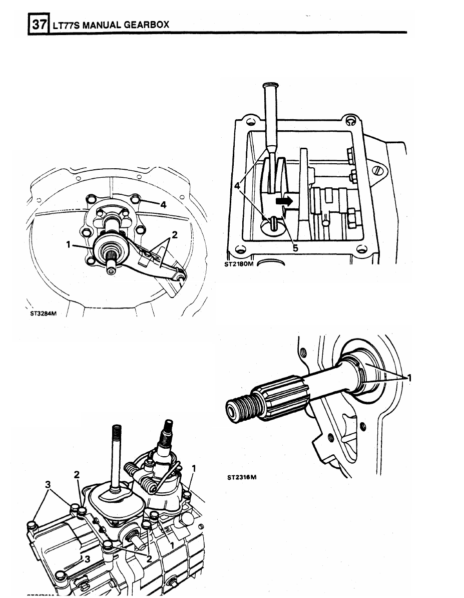
DISMANTLE
Bell
housing
1.
Remove clutch release bearing.
2. Remove screw and spring clip and remove
release lever.
3.
Remove "C" clip from pivot post.
4.
Remove
six
bolts and bell housing.
EXTENSION HOUSING
1.
Remove snap ring retaining oil seal collar.
GEAR SELECTOR HOUSING
1.
Remove four bolts and remove main gearbox
selector housing.
2.
Remove transfer box housing.
3. Remove remaining
bolts and remove remote
housing.
4.
Drive out quadrant roll pin.
5.
Move selector shaft forward to remove
quadrant.
Нет комментариевНе стесняйтесь поделиться с нами вашим ценным мнением.
Текст