Volvo XC90 Recharge Plug-in Hybrid (2021 year). Manual in english — page 23

DRIVER SUPPORT
* Option/accessory.
389
Park Assist Pilot
*
messages
Messages for Park Assist Pilot (PAP
123
) may
be displayed in the instrument panel and/or
the center display. Several examples are pro-
vided below.
Message
Meaning
Park Assist System
Sensors blocked, cleaning needed
One or more of the sensors are blocked. Check and clean/remove the obstacle as soon as possible.
Park Assist System
Unavailable Service required
The system is not functioning as intended. Contact a workshop
A
.
A
An authorized Volvo workshop is recommended.
A text message can be erased by briefly press-
ing the
button in the center of the right-
side steering wheel keypad.
If a message cannot be erased, contact a
workshop
A
.
Related information
•
•
123
Park Assist Pilot
-------------------------------------------------------------------------------------------------------------------------------------------------------------
DRIVER SUPPORT
* Option/accessory.
390
Radar sensor
The radar sensor is used by several driver
support systems to detect other vehicles.
Location of radar sensor
The radar sensor is used by the following func-
tions:
•
Distance Alert
*
•
Adaptive Cruise Control
*
•
Pilot Assist
*
•
Lane Keeping Aid
•
City Safety
•
Steering assistance at risk of collision
Any modifications to the radar sensor may
make its use illegal.
Related information
•
Driver support systems (p. 280)
•
Camera/radar sensor limitations (p. 393)
•
Recommended camera and radar sensor
maintenance (p. 396)
•
-------------------------------------------------------------------------------------------------------------------------------------------------------------

DRIVER SUPPORT
}}
* Option/accessory.
391
Radar sensor type approval
The type approval for the vehicle's radar units
for adaptive cruise control
*
(ACC
124
), Pilot
Assist
*
and BLIS
*
125
are found here.
Market
ACC & PA
BLIS
Type approval
Canada
✓
FCC ID: L2C0054TR IC: 3432A-0054TR
FCC ID: L2C0055TR IC: 3432A-0055TR
✓
Canada Standard RSS-310
USA
✓
FCC ID: L2C0054TR IC: 3432A-0054TR
FCC ID: L2C0055TR IC: 3432A-0055TR
✓
FCC ID: NBG01RS4
This device complies with Part 15 of the FCC
Rules and with Industry Canada license-
exempt RSS standard(s). Operation is subject
to the following two conditions:
(1) This device may not cause harmful
interference, and
(2) This device must accept any interference
received, including interference that may
cause undesired operation.
Ce dispositif de radiocommunication de
catégorie II respecte la norme CNR-310
d’Industrie Canada. Le présent appareil est
conforme aux CNR d'Industrie Canada
applicables aux appareils radio exempts de
licence. L'exploitation est autorisée aux deux
conditions suivantes:
(1) l'appareil ne doit pas produire de brouillage,
et
(2) l'utilisateur de l'appareil doit accepter tout
brouillage radioélectrique subi, même si le
brouillage est susceptible d'en compromettre
le fonctionnement.
Cet appareil est conforme aux CNR d’Industrie
Canada a applicables aux appareils radio
exempts de licence. L’exploitation est
autorisée à condition que l'appareil ne
produise pas de brouillage préjudiciable et
qu'il accepte tout brouillage, même celui
susceptible d'en compromettre le
fonctionnement.
CAUTION TO USERS: Changes or
modifications not expressively approved by
the party responsible for compliance could
void the user's authority to operate the
equipment. The term “IC:” before the radio
certification number only signifies that
Industry Canada technical specifications were
met.
Note: This equipment complies with radiation
exposure limits set forth for an uncontrolled
124
Adaptive Cruise Control
125
Blind Spot Information
-------------------------------------------------------------------------------------------------------------------------------------------------------------
||
DRIVER SUPPORT
* Option/accessory.
392
environment. This equipment should be
installed and operated with minimum distance
of 20 cm between the radiator and your body.
For detailed information about type approval,
go to volvocars.com/support.
Related information
•
•
•
•
-------------------------------------------------------------------------------------------------------------------------------------------------------------
DRIVER SUPPORT
}}
* Option/accessory.
393
Camera
The camera is used by several driver support
systems to e.g. detect lane marker lines or
road signs.
Location of the camera
The camera is used by the following functions:
•
Adaptive Cruise Control
*
•
Pilot Assist
*
•
Lane Keeping Aid
*
•
Steering assistance at risk of collision
•
City Safety
•
Driver Alert Control
*
•
Road Sign Information
*
•
Active high beams
*
•
Park Assist
*
Related information
•
Driver support systems (p. 280)
•
Camera/radar sensor limitations (p. 393)
•
Recommended camera and radar sensor
maintenance (p. 396)
Camera/radar sensor limitations
The camera and radar sensor used by several
of the driver support functions has certain
limitations, which also affect the functions
using the camera and radar sensor. The driver
should be aware of the following limitations:
-------------------------------------------------------------------------------------------------------------------------------------------------------------
||
DRIVER SUPPORT
394
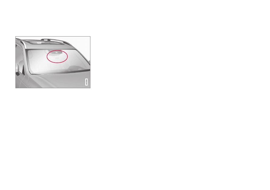
Common camera and radar limitations
Obstructed camera
The area marked in the illustration must be cleaned
regularly and kept free of decals, objects, solar film,
etc.
The camera is located on the upper interior
section of the windshield along with the radar
sensor.
Do not place, affix or mount anything on the
inside or outside of the windshield, or in front
of or around the camera and radar sensor –
this could disrupt camera and radar-based
functions. It could cause functions to be
reduced, deactivated completely or to produce
an incorrect function response.
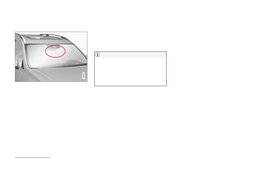
High temperatures
If the temperature in the passenger compart-
ment is very high, the camera/radar sensor
will switch off temporarily for
approx. 15 minutes after the engine is started
to protect its electronic components. When
the temperature has cooled sufficiently, the
camera/radar sensor will automatically restart.
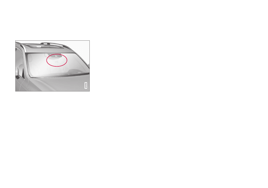
Damaged windshield
Failure to take action could result in
reduced performance for the driver support
systems that use the camera and radar
unit. It could cause functions to be
reduced, deactivated completely or to pro-
duce an incorrect function response.
To avoid the risk of malfunction of the driver
support systems that use the radar sensor, the
following also apply:
•
If there are cracks, scratches or stone
chips on the windshield in front of any of
the camera and radar sensor "windows"
and this covers an area of
about 0.5 × 3.0 mm (0.02 × 0.12 in.) or
more, contact a workshop to have the
windshield replaced
126
.
•
Volvo advises
against
repairing cracks,
scratches or stone chips in the area in
front of the camera and radar sensor – the
entire windshield should instead be
replaced.
•
Before replacing the windshield, contact a
workshop
126
to verify that the right wind-
shield has been ordered and installed.
•
The same type of windshield wipers or
wipers approved by Volvo should be used
for replacement.
•
If the windshield is replaced, the camera
and radar sensor must be recalibrated by a
workshop
126
to help ensure proper func-
tioning of all of the vehicle's camera and
radar-based systems.
Additional radar limitations
Vehicle speed
The radar sensor's ability to detect a vehicle
ahead is significantly reduced if the speed of
the vehicle ahead differs greatly from your
vehicle's speed.
126
An authorized Volvo workshop is recommended.
-------------------------------------------------------------------------------------------------------------------------------------------------------------
DRIVER SUPPORT
}}
* Option/accessory.
395
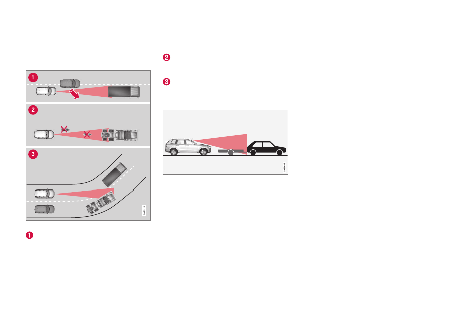
Limited field of vision
The radar sensor has a limited field of vision. In
some situations, it may detect a vehicle later
than expected or not at all.
The radar sensor's field of vision
The radar sensor's detection of vehicles
very close to your vehicle may be delayed
in certain situations, e.g. if a vehicle pulls
in between your vehicle and the vehicle
directly ahead.
Small vehicles, such as motorcycles, or
vehicles that are not driving in the center
of the lane may remain undetected.
In curves, the radar may detect the a dif-
ferent vehicle than intended or lose sight
of a target vehicle.
Low trailers
Low trailer in the radar shadow
Low trailers may also be difficult or even
impossible for the radar to detect. The driver
should be extra alert when driving behind vehi-
cles towing low trailers when Adaptive Cruise
Control
*
or Pilot Assist
*
is activated.
Additional camera limitations
Reduced visibility
Cameras have the same limitations as the
human eye. In other words, their “vision" is
impaired by adverse weather conditions such
as heavy snowfall/rain, dense fog, swirling
dust/snow, etc. These conditions may reduce
the function of systems that depend on the
camera or cause these systems to temporarily
stop functioning.
Strong sunlight, reflections from the road sur-
face, ice or snow covering the road, a dirty
road surface, or unclear lane marker lines may
drastically reduce the camera’s ability to
detect the side of a lane, a pedestrian, a
cyclist, a large animal or another vehicle.
-------------------------------------------------------------------------------------------------------------------------------------------------------------
||
DRIVER SUPPORT
* Option/accessory.
396
Additional Park Assist Camera
*
limitations
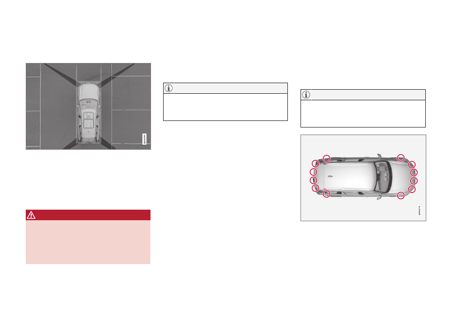
Blind sectors
There are "blind" sectors between the cameras' fields
of vision.
With the Park Assist Camera's 360° view
*
selected, objects/obstacles may not be
detected if they are located in the "joints"
where the edges of the individual camera
views meet.
WARNING
Even if it seems as though only a fairly
small section of the screen image is
obstructed, this may mean that a relatively
large sector is hidden and obstacles there
may not be detected until they are very
near the vehicle.
Lighting conditions
The camera image is automatically adjusted
according to the current lighting conditions.
This means that the brightness and quality of
the image may vary slightly. Poor lighting con-
ditions may result in reduced image quality.
A bike carrier and other accessories moun-
ted on the rear of the vehicle can obscure
the camera's view.
Related information
•
•
•
Recommended camera and radar sensor
maintenance (p. 396)
•
•
Volvo Cars support site (p. 21)
Recommended camera and radar
sensor maintenance
In order for the camera and radar units to
function properly, they must be kept free of
dirt, ice, snow, etc. and should be washed
regularly with water and car washing deter-
gent.
Dirt, ice and snow covering the sensors
could cause false warnings, reduced func-
tion, or no function.
Location of the Park Assist sensors
-------------------------------------------------------------------------------------------------------------------------------------------------------------
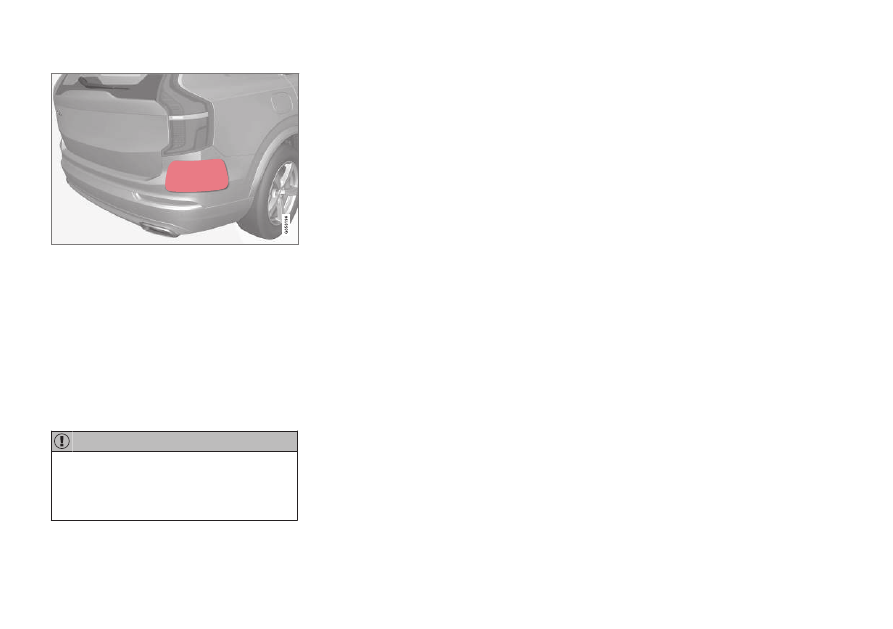
DRIVER SUPPORT
* Option/accessory.
397
Location of rear radar sensors. Keep the marked area
clean (on both the left and right sides of the vehicle).
•
For best possible performance, it is impor-
tant to keep the areas in front of the sen-
sors clean.
•
Do not attach any objects, tape or decals
to the surface of the sensors.
•
Clean the camera lenses regularly using
lukewarm water and car washing deter-
gent. Wash gently to avoid scratching the
lens.
Only a workshop may perform mainte-
nance on driver support components – an
authorized Volvo workshop is recom-
mended.
Related information
•
•
•
Camera/radar sensor limitations (p. 393)
•
-------------------------------------------------------------------------------------------------------------------------------------------------------------

DRIVER SUPPORT
398
Camera and radar unit symbols
and messages
Here are examples of some of the messages
and symbols related to the camera and radar
units that may be displayed in the instrument
panel.
Sensor blocked
If this symbol and the message
Windscreen sensor
Sensor
blocked, see Owner's manual
is
displayed in the instrument panel, it
means that the camera and radar unit are
unable to detect other vehicles, cyclists,
pedestrians and large animals in front of the
vehicle and that the vehicle's camera and
radar-based functions may be obstructed.
The following table shows some of the situa-
tions that can cause the message to be dis-
played, and suggested actions:
Cause
Action
The area of the windshield in front of the camera/radar sensor is
dirty or covered by ice or snow.
Clean the windshield in front of the camera/radar sensor and remove dirt, ice
and snow.
Thick fog, heavy rain or snow is blocking the radar signals or the
camera's range of visibility.
No action. Heavy precipitation may sometimes prevent the camera/radar sensor
from functioning.
Water or snow is spraying/swirling up and blocking the radar
signals or the camera's range of visibility.
No action. Very wet or snow-covered roads may sometimes prevent the cam-
era/radar sensor from functioning.
There is dirt between the inside of the windshield and the cam-
era/radar sensor.
Consult a workshop to have the area of the windshield on the inside of the cam-
era's casing cleaned. An authorized Volvo workshop is recommended.
Bright sunlight.
No action. The camera/radar sensor will reset automatically when lighting con-
ditions improve.
-------------------------------------------------------------------------------------------------------------------------------------------------------------
DRIVER SUPPORT
399
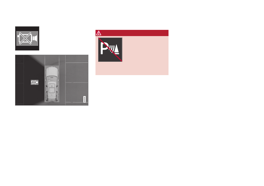
Defective camera
If a camera sector is dark and
contains this symbol, this
indicates that the camera is
not functioning properly.
The vehicle's left-side camera is malfunctioning.
A dark camera sector may also be displayed in
the following situations, but
without
the
defective camera symbol:
•
a door is open
•
the tailgate is open
•
a rearview mirror is folded in
Rear Park Assist Camera
WARNING
Be extra cautious when
reversing if this symbol is
shown when a trailer, bike
carrier or similar is
attached and electrically
connected to the vehicle.
The symbol indicates that
the rear parking assist sensors are
deacti-
vated
and will not warn of any obstacles.
Related information
•
•
•
Camera/radar sensor limitations (p. 393)
•
-------------------------------------------------------------------------------------------------------------------------------------------------------------
ELECTRIC MOTOR AND CHARGING
402
General information about electric
vehicles
Recharge vehicles are driven just like any
other vehicle, but certain functions differ from
a vehicle powered exclusively by gasoline.
The electric motor powers the vehicle primar-
ily at low speeds; the gasoline engine is used
at higher speeds or during more active driv-
ing.
The instrument panel displays Recharge-spe-
cific information - charging information,
selected drive mode, distance to discharged
battery and hybrid battery charge level.
Different drive modes can be selected while
driving, e.g. electric power only or, if more
power is needed, a combination of electric and
gasoline power. The vehicle calculates a com-
bination of driveability, driving experience,
environmental impact and fuel economy for
the selected drive mode.
In order to function optimally, the hybrid bat-
tery (and its electrical drive systems) and the
gasoline engine (and its drive systems) must
be at the correct operating temperature. Bat-
tery capacity can be considerably reduced if
the battery is too cold or too hot. Precondi-
tioning prepares the vehicle's drive systems
and passenger compartment before driving to
help reduce both wear and energy consump-
tion. It also helps increase the hybrid battery's
range.
The hybrid battery which powers the electric
motor is recharged using the charging cable. It
can also be recharged during light braking and
through engine braking in gear position
B
. The
combustion engine can also help recharge the
hybrid battery.
Important
No electrical current
Keep in mind that if there is no electrical cur-
rent to the vehicle, i.e. the ignition is switched
off or the start battery is discharged, certain
functions such as power brakes, power steer-
ing, etc. will be limited.
WARNING
The power brakes only work when the
electric motor or combustion engine is run-
ning.
Towing not permitted
Never tow the vehicle behind another vehicle,
as this could damage the electric motor.
Exterior engine noise
Because there is no sound from the engine
when only the electric motor is running, the
vehicle is equipped with artificial exterior
background noise. This sound is intended to
help warn children, pedestrians, cyclists, ani-
mals, etc. outside the vehicle of the vehicle's
approach.
High-voltage electrical current
WARNING
A number of electrical components in the
vehicle use high-voltage current and can be
extremely dangerous if handled incorrectly.
These components and any orange wiring
in the vehicle may only be handled by
trained and qualified Volvo service techni-
cians.
Related information
•
Charging the hybrid battery (p. 403)
•
•
•
Starting and stopping preconditioning
(p. 235)
•
•
Automatic transmission (p. 439)
•
-------------------------------------------------------------------------------------------------------------------------------------------------------------
ELECTRIC MOTOR AND CHARGING
}}
403
Charging the hybrid battery
In addition to the conventional fuel tank, your
vehicle is also equipped with a rechargeable
lithium-ion hybrid battery.
WARNING
California Proposition 65
Operating, servicing and maintaining a pas-
senger vehicle can expose you to chemi-
cals including engine exhaust, carbon mon-
oxide, phthalates, and lead, which are
known to the State of California to cause
cancer and birth defects or other reproduc-
tive harm. To minimize exposure, avoid
breathing exhaust, do not idle the engine
except as necessary, service your vehicle in
a well ventilated area and wear gloves or
wash your hands frequently when servicing
your vehicle. For more information go to
The hybrid battery can be recharged using the
charging cable stored in a storage space in the
cargo compartment.
WARNING
The hybrid electrical system in your vehicle
uses high voltage electrical current. Any
damage to this system or to the hybrid bat-
tery may result in the danger of overheat-
ing, fire, or serious injury. If the vehicle is
involved in a collision or subjected to flood-
ing, fire, etc., have it inspected by a trained
and qualified Volvo service technician. Prior
to this inspection, the vehicle should be
parked outdoors at a safe distance from
any building or potentially flammable mate-
rials.
The hybrid battery's charging time depends on
the charging current used.
The capacity of the hybrid battery dimin-
ishes somewhat with age and use, which
could result in increased use of the gaso-
line engine and consequently, slightly
higher fuel consumption.
WARNING
If the hybrid battery needs to be replaced,
this may only be done by a Volvo retailer or
authorized Volvo workshop.
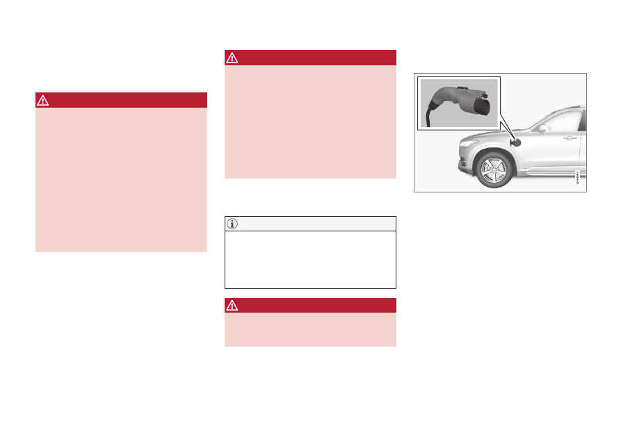
Charging cable handle and charging
socket
Charging cable handle and charging socket.
Charging status is indicated in three ways:
•
Indicator on the charging cable's control
module.
•
Indicator light in the vehicle's charging
socket.
•
Images and text in the instrument panel.
The start battery is charged while the hybrid
battery is charging and stops charging when
the hybrid battery is fully charged.
If the hybrid battery's temperature is below
-10
º
C (14
º
F) or above 40
º
C (104
º
F), some
of the vehicle's functions may be reduced or
not available at all.
-------------------------------------------------------------------------------------------------------------------------------------------------------------
||
ELECTRIC MOTOR AND CHARGING
* Option/accessory.
404
The electric motor cannot be used if the bat-
tery's temperature is too low or too high. If the
PURE drive mode is selected, the gasoline
engine will start.
Charging with fixed control module in
accordance with mode 3
1
In certain markets, the control module is
installed within a charging station connected
to an electrical outlet. In this case, the charg-
ing cable does not have its own control mod-
ule. You must therefore use the charging sta-
tion's charging cable and follow the instruc-
tions on the charging station.
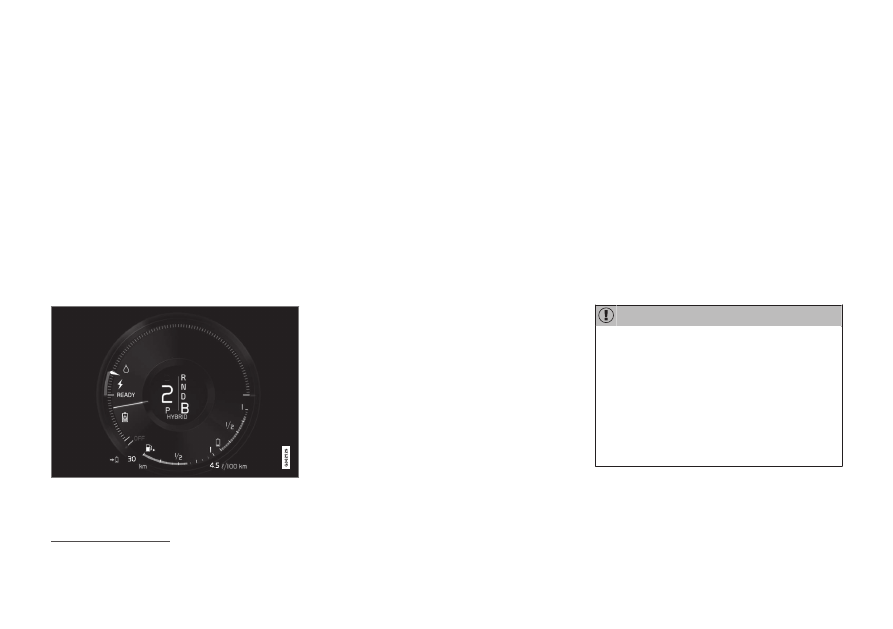
Energy recovery during braking
Indicator in the instrument panel during energy
recovery.
Energy is regenerated to the battery when the
brake pedal is depressed lightly or during
engine braking.
The function is available in all drive modes
together with gear selector position
D
or
B
.
Related information
•
•
•
Opening and closing the charging socket
cover (p. 409)
•
Initiating hybrid battery charging (p. 410)
•
Stopping hybrid battery charging (p. 418)
•
Charging status in the charging cable's
control module (p. 413)
•
Charging status in the vehicle's charging
socket (p. 412)
•
Charging status in the instrument panel
(p. 416)
•
Hybrid symbols and messages in the
instrument panel (p. 419)
•
Automatic transmission (p. 439)
•
•
Long-term storage of vehicles with hybrid
batteries (p. 421)
•
Charging current
Charging current is used to charge the hybrid
battery and precondition the vehicle. Charg-
ing is performed by connecting a charging
cable between the vehicle's charging socket
and a 120/240 V electrical socket (alternat-
ing current).
When the charging cable is activated, a mes-
sage will be displayed in the instrument panel
and an indicator light in the vehicle's charging
socket will illuminate. Charging current is pri-
marily used for battery charging, but is also
used for preconditioning. The vehicle's start
battery is charged along with the hybrid bat-
tery.
Never detach the charging cable from the
120/240 V outlet (AC, alternating current)
while charging is in progress – the
120/240 V outlet could be damaged in
such circumstances. Always interrupt
charging first and then disconnect the
charging cable – first from the vehicle's
charging socket and then from the
120/240 V outlet.
1
European standard - EN 61851-1.
-------------------------------------------------------------------------------------------------------------------------------------------------------------
ELECTRIC MOTOR AND CHARGING
405
Make sure that the fuse to the wall outlet
can handle the current specified for the
charging cable.
•
In extremely cold or hot weather, part
of the charging current is used to heat/
cool the hybrid battery and the passen-
ger compartment, resulting in a longer
charging time.
•
The charging time is longer if precondi-
tioning has been selected. The time
required depends primarily on the
ambient temperature.
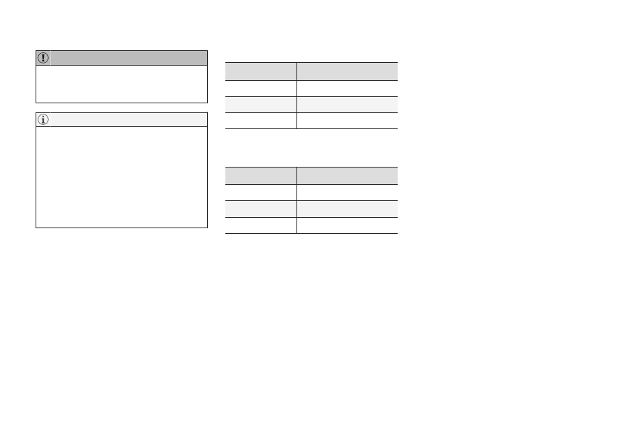
Charging time
Charging time may vary. The following charg-
ing times apply when charging is not affected
by current being drawn from the climate sys-
tem or any other function. If charging seems
to be taking more time than shown in the
table, this should be investigated.
Charging times for charging with 200-240 V
Amperage (A)
A
Charging time (hours)
6
8
10
4
16
3
A
Maximum charging current may vary from market to mar-
ket.
Charging times for charging with 100-120 V
Amperage (A)
A
Charging time (hours)
6
17
10
9
16
6
A
Maximum charging current may vary from market to mar-
ket.
Fuse
There are normally several 120/240 V power
consumers in one fuse circuit, which means
that more than one power consumer (e.g.
lighting, vacuum cleaner, electric drill, etc.)
may use the same fuse.
Related information
•
•
Charging status in the charging cable's
control module (p. 413)
•
Charging status in the instrument panel
(p. 416)
•
Charging status in the vehicle's charging
socket (p. 412)
•
Starting and stopping preconditioning
(p. 235)
•
-------------------------------------------------------------------------------------------------------------------------------------------------------------
ELECTRIC MOTOR AND CHARGING
406
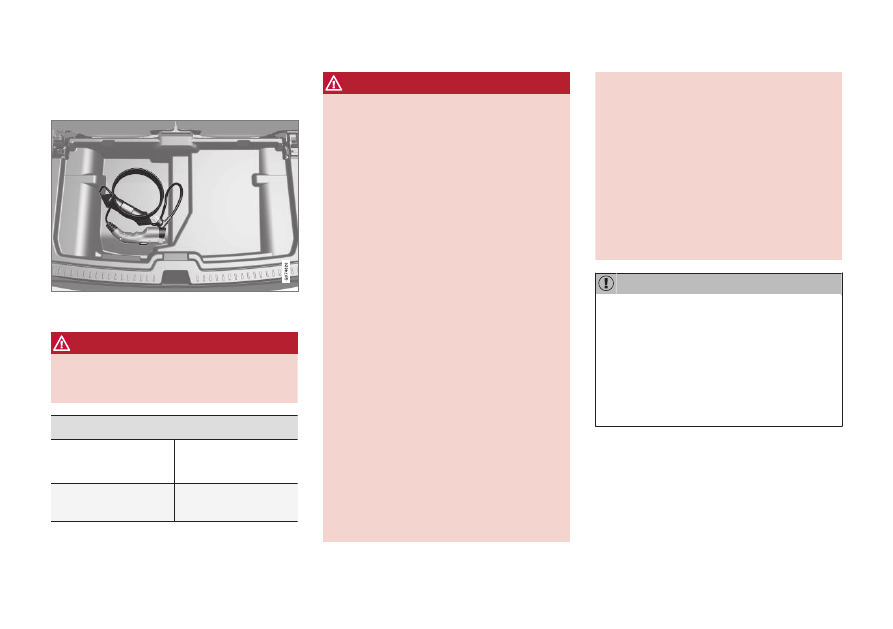
Charge cable
The charging cable and its control module are
used to charge the vehicle's hybrid battery.
The charging cable is stored in a storage compart-
ment under the cargo compartment floor.
WARNING
Only use the charging cable provided with
your vehicle or a replacement cable pur-
chased from a Volvo retailer.
Specifications, charging cable
Enclosure class
Compliance
IP67
SAE J1772
Ambient tempera-
ture
-32
º
C to 50
º
C
(-25
º
F till 122
º
F)
WARNING
•
The charging cable must be grounded
when in use. It is equipped with a cord
with a grounding conductor and a
grounding plug. The plug must be
inserted into an appropriate outlet that
is properly installed and grounded in
accordance with all local codes and
ordinances and is not damaged in any
way.
•
Children should be supervised when in
the vicinity of the charging cable when
it is plugged in.
•
High voltage is present in your electric
meter housing and power distribution
service panel. Contact with high volt-
age can cause death or serious per-
sonal injury.
•
Do not use the charging cable if it is
damaged in any way. A damaged or
malfunctioning charging cable may
only be repaired by a workshop – an
authorized Volvo workshop is recom-
mended.
•
Always position the charging cable so
that it will not be driven over, stepped
on, tripped over or otherwise damaged,
or cause personal injury.
•
Disconnect the charger from the wall
outlet before cleaning it.
•
Never connect the charging cable to an
extension cord or a multiple plug
socket.
•
Do not use one or more adapters
between the charging cable and the
electric outlet.
•
Do not use an external timer between
the charging cable and the electrical
outlet.
Also, refer to the manufacturer's instruc-
tions for using the charging cable and its
components.
Power strips, external timers, adapters,
extension cords, surge protectors or similar
devices must not be used together with
the charging cable since this may involve a
risk of fire, electric shocks, etc.
Do not use an external timer or adapter
between the 120/240 V outlet (AC, alter-
nating current) and the charging cable.
-------------------------------------------------------------------------------------------------------------------------------------------------------------
Нет комментариевНе стесняйтесь поделиться с нами вашим ценным мнением.
Текст