Volvo S90 Recharge Plug-in Hybrid (2021 year). Manual in english — page 34
WHEELS AND TYRES
}}
}}
583
Using a puncture repair kit
The emergency puncture repair kit (TMK
9
)
can be used to seal a puncture. Read through
all instructions before use.
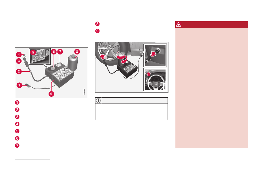
Overview
Electrical cable
Air hose
Pressure reducing valve
Protective cap
Label, maximum permitted speed
Bottle holder (orange cap)
Pressure gauge
Sealing fluid bottle
Switch
Connecting
Do not break the bottle's seal before use.
The seal is broken automatically when the
bottle is screwed in.
WARNING
Please keep the following points in mind
when using the tyre sealing system:
•
The sealing fluid bottle contains 1) rub-
ber latex, natural and 2) ethanediol.
These substances are harmful if swal-
lowed.
•
The contents of this bottle may cause
allergic skin reactions or otherwise be
potentially harmful to the respiratory
tract, the skin, the central nervous sys-
tem, and the eyes.
Precautions:
•
Store out of the reach of children.
•
Harmful if ingested.
•
Avoid prolonged or repeated contact
with the skin. If sealing fluid has come
into contact with your clothes, remove
them.
•
Wash thoroughly after handling.
First aid:
•
Skin: Wash affected areas of skin with
soap and water. Get medical attention
if symptoms occur.
•
Eyes: Flush with plenty of water for
least 15 minutes, occasionally lifting
9
Temporary Mobility Kit
-------------------------------------------------------------------------------------------------------------------------------------------------------------
||
WHEELS AND TYRES
584
the upper and lower eyelids. Get medi-
cal attention if symptoms occur.
•
Inhalation: Move the exposed person
to fresh air. If irritation persists, get
medical attention.
•
Ingestion: Do NOT induce vomiting
unless directed to do so by medical
personnel. Get medical attention.
•
Disposal: Dispose of this material and
its container at a hazardous or special
waste collection point.
WARNING
Do not remove the bottle or air hose when
the puncture repair kit is being used.
1.
Preparations
Set up the warning triangle and activate
the hazard warning lights if a tyre is being
sealed in a trafficked location.
If the puncture was caused by a nail or
similar, allow this to remain in the tyre. It
helps to seal the hole.
2. Detach the decal for maximum permitted
speed that is affixed on one side of the
compressor. Affix it visibly on the wind-
screen as a reminder to observe the speed
limit. You should not drive faster than
80 km/h (50 mph) after the emergency
tyre repair kit has been used.
3. Check that the switch is in position
0
(Off), and locate the electrical cable and
the air hose.
4. Unscrew the orange-coloured cap from
the compressor, and unscrew the cork
from the sealing fluid bottle.
5. Screw in the bottle to the bottom of the
bottle holder.
The bottle and the bottle holder are equip-
ped with a reverse catch to prevent seal-
ant leakage. When the bottle is screwed in
it cannot be unscrewed from the bottle
holder again. The bottle must be removed
at a workshop
10
.
WARNING
Do not unscrew the bottle, it is equipped
with a reverse catch to prevent leakage.
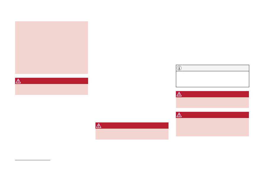
6. Unscrew the tyre's dust cap and screw in
the air hose's valve connection to the bot-
tom of the thread on the tyre's air valve.
Check that the pressure reducing valve on
the air hose is fully screwed in.
7.
Begin puncture repair
Connect the electrical cable to the closest
12 V socket and start the car.
Make sure that none of the other 12 V
sockets is in use when the compressor is
operating.
WARNING
Do not leave children in the car without
supervision when the engine is running.
WARNING
Inhaling car exhaust fumes could result in
danger to life. Never leave the engine run-
ning in sealed areas or areas that lack suffi-
cient ventilation.
10
An authorised Volvo workshop is recommended.
-------------------------------------------------------------------------------------------------------------------------------------------------------------
WHEELS AND TYRES
}}
585
8. Start the compressor by flicking the
switch to position
I
(On).
When the compressor starts, the pressure
can increase up to 6 bar (88 psi), but the
pressure drops after about 30 seconds.
WARNING
Never stand next to the tyre when the
compressor is running. If cracks or uneven-
ness arise then the compressor must be
switched off immediately. The journey
should not be continued. Call roadside
assistance for recovery to a tyre centre.
Volvo recommends an authorised tyre cen-
tre.
9. Inflate the tyre for 7 minutes.
The compressor must not be operated for
longer than 10 minutes - risk of overheat-
ing.
10. Switch off the compressor to check the
pressure on the pressure gauge. Minimum
pressure is 1.8 bar (22 psi) and maximum
is 3.5 bar (51 psi). Release air using the
pressure reducing valve if the tyre pres-
sure is too high.
WARNING
If the pressure is below 1.8 bar (22 psi)
then the hole in the tyre is too big. The jour-
ney should not be continued. Call roadside
assistance for recovery to a tyre centre.
Volvo recommends an authorised tyre cen-
tre.
11. Switch off the compressor and detach the
electrical cable.
12. Unscrew the air hose from the tyre valve
and refit the dust cap on the tyre.
•
After a tyre has been inflated, always
refit the dust cap in order to avoid dam-
age to the valve from gravel, dirt, etc.
•
Only use plastic dust caps. Metal dust
caps can rust and become difficult to
unscrew.
13. Fit the protective cap on the air hose in
order to avoid leakage of the remaining
sealing fluid. Place the equipment in the
cargo area.
14. As soon as possible, drive at least 3 km
(2 miles) at a maximum speed of 80 km/h
(50 mph) so that the sealing fluid can seal
the tyre, and then perform a follow-up
check.
WARNING
Sealant will spurt out of the puncture dur-
ing the first few rotations of the tyre. Make
sure that nobody is standing near the car
and gets the sealing fluid splashed onto
them when the car is driven away. The dis-
tance should be at least 2 metres (7 feet).
15.
Follow-up inspection
Connect the air hose on the tyre valve and
screw in the valve connection to the bot-
tom of the tyre valve's thread. The com-
pressor must be switched off.
-------------------------------------------------------------------------------------------------------------------------------------------------------------
||
WHEELS AND TYRES
586
16. Read the tyre pressure on the pressure
gauge.
•
If it is below 1.3 bar (19 psi) then the
tyre is insufficiently sealed. The journey
should not be continued. Call roadside
assistance for recovery.
•
If the tyre pressure is higher than
1.3 bar (19 psi), the tyre must be infla-
ted to the pressure specified in accord-
ance with the tyre pressure label on the
driver's side door pillar (1 bar = 100 kPa
= 14.5 psi). Release air using the pres-
sure reducing valve if the tyre pressure
is too high.
WARNING
Check the tyre pressure regularly.
Volvo recommends that the car is driven to the
nearest authorised Volvo workshop for the
replacement/repair of the damaged tyre.
Advise the workshop that the tyre contains
sealing fluid.
The sealing fluid bottle and hose must be
replaced after use. Volvo recommends that
these replacements be performed by an
authorised Volvo workshop.
WARNING
Maximum mileage with tyres containing
sealing fluid is 200 km (120 miles).
The compressor is an electrical device. Fol-
low local regulations related to waste man-
agement.
Related information
•
Recommended tyre pressure (p. 570)
•
Emergency puncture repair kit (p. 582)
•
Inflating tyres with the compressor from
the puncture repair kit (p. 586)
Inflating tyres with the compressor
from the puncture repair kit
The car's original tyres can be inflated using
the compressor in the emergency puncture
repair kit.
1. The compressor must be switched off.
Make sure that the switch is in position
0
(Off), and take out the electrical cable and
the air hose.
2. Unscrew the tyre's dust cap and screw in
the air hose's valve connection to the bot-
tom of the thread on the tyre's air valve.
Check that the pressure reducing valve on
the air hose is fully screwed in.
3. Connect the electrical cable to the closest
12 V socket and start the car.
WARNING
Inhaling car exhaust fumes could result in
danger to life. Never leave the engine run-
ning in sealed areas or areas that lack suffi-
cient ventilation.
WARNING
Do not leave children in the car without
supervision when the engine is running.
-------------------------------------------------------------------------------------------------------------------------------------------------------------
WHEELS AND TYRES
587
4. Start the compressor by flicking the
switch to position
I
(On).
Risk of overheating. The compressor must
not run for more than 10 minutes.
5. Inflate the tyre to the pressure specified
on the tyre pressure label on the driver
side door pillar. Release air using the pres-
sure reducing valve if the tyre pressure is
too high.
6. Switch off the compressor. Detach the air
hose and the electrical cable.
7. Refit the dust cap on the tyre.
•
After a tyre has been inflated, always
refit the dust cap in order to avoid dam-
age to the valve from gravel, dirt, etc.
•
Only use plastic dust caps. Metal dust
caps can rust and become difficult to
unscrew.
The compressor is an electrical device. Fol-
low local regulations related to waste man-
agement.
Related information
•
Recommended tyre pressure (p. 570)
•
Using a puncture repair kit (p. 583)
•
-------------------------------------------------------------------------------------------------------------------------------------------------------------
LOADING, STORAGE AND PASSENGER COMPARTMENT
* Option/accessory.
590
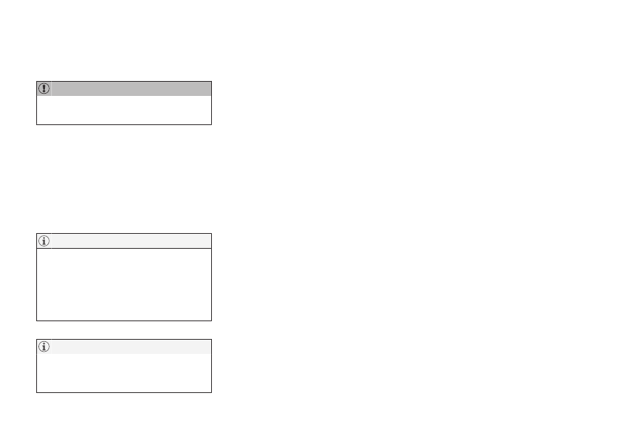
Passenger compartment interior
Overview of the passenger compartment's
interior and storage locations.
Front seat
Storage compartment in the door panel and by the
steering wheel, glovebox and sun visors.
Storage spaces with cup holder, electrical socket,
mesh pocket
*
and USB port in the tunnel console.
Rear seat
Storage compartment in the door panel, cup holder
*
in the centre seat backrest, storage pocket
*
on the
front seat backrest and also USB ports in the tunnel
console.
WARNING
Keep loose objects such as mobile phones,
cameras, remote controls for accessories,
etc. in the glove compartment or other
compartments. Otherwise they may injure
people in the car in the event of sudden
braking or a collision.
Keep in mind that high gloss surfaces, for
example, are easily scratched by metal
objects. Do not place keys, phones and
other items on sensitive surfaces.
Related information
•
•
•
•
•
-------------------------------------------------------------------------------------------------------------------------------------------------------------
LOADING, STORAGE AND PASSENGER COMPARTMENT
}}
* Option/accessory.
591
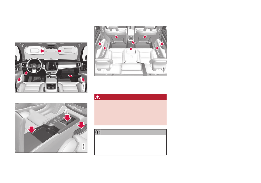
Tunnel console
The tunnel console is located between the
front seats.
Storage compartment with cup holder.
Storage compartment with 12 V socket
and USB port under the armrest.
Climate controls for the rear seat climate
functions
*
or storage compartment. There
are also USB ports underneath.
WARNING
Keep loose objects such as mobile phones,
cameras, remote controls for accessories,
etc. in the glove compartment or other
compartments. Otherwise they may injure
people in the car in the event of sudden
braking or a collision.
Keep in mind that high gloss surfaces, for
example, are easily scratched by metal
objects. Do not place keys, phones and
other items on sensitive surfaces.
One of the detectors for the alarm
*
is
located under the tunnel console's cup
holder. Avoid leaving coins, keys and other
metal objects in the cup holder, since this
may trigger the alarm.
The USB sockets can be used for charging
a mobile phone or tablet, for example. Only
the front USB input can be used to play
media in the car's audio system.
Related information
•
Passenger compartment interior (p. 590)
•
•
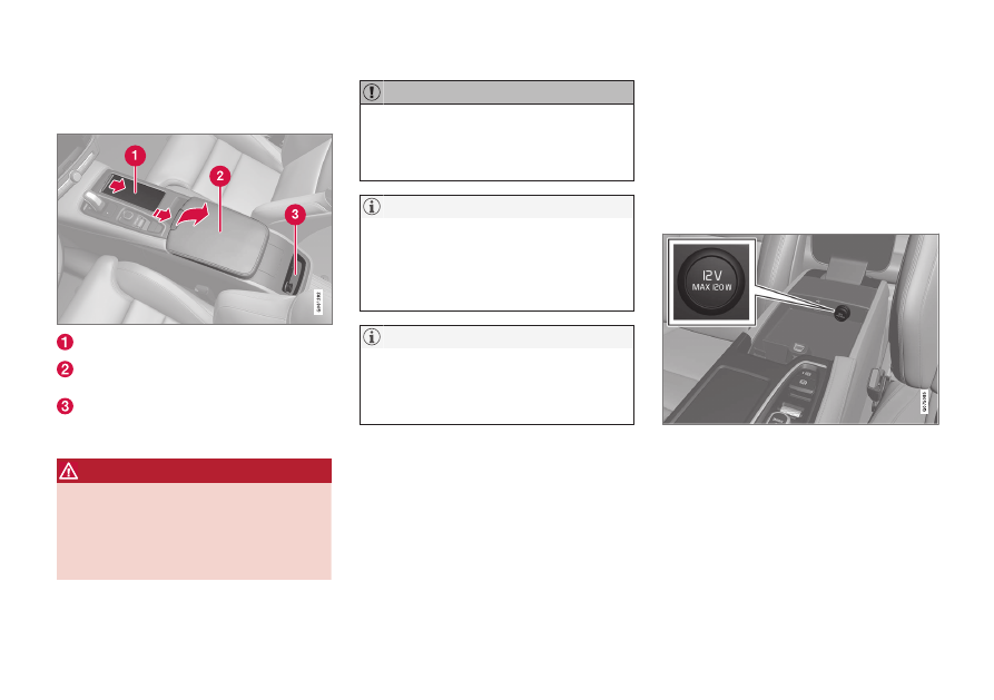
Electrical sockets
There is one 12V electrical socket in the tun-
nel console and one 12V electrical socket
*
in
the luggage compartment/cargo area.
If a problem occurs with an electrical socket,
contact a workshop - an authorised Volvo
workshop is recommended.
12 V electrical socket
12 V electrical socket in tunnel console, front seat.
The 12 V sockets can be used for various
accessories designed for this, such as music
players, cooler boxes and mobile phones.
-------------------------------------------------------------------------------------------------------------------------------------------------------------
||
LOADING, STORAGE AND PASSENGER COMPARTMENT
* Option/accessory.
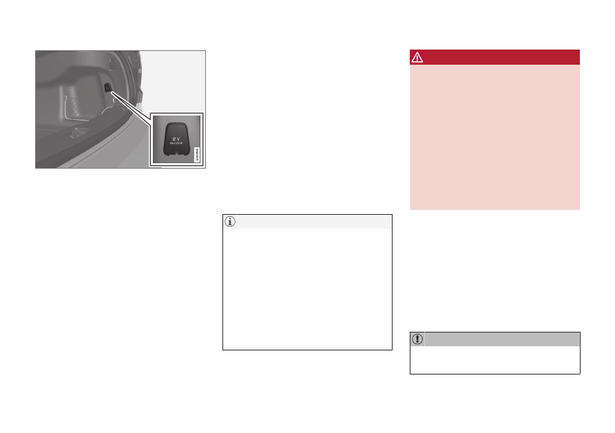
592
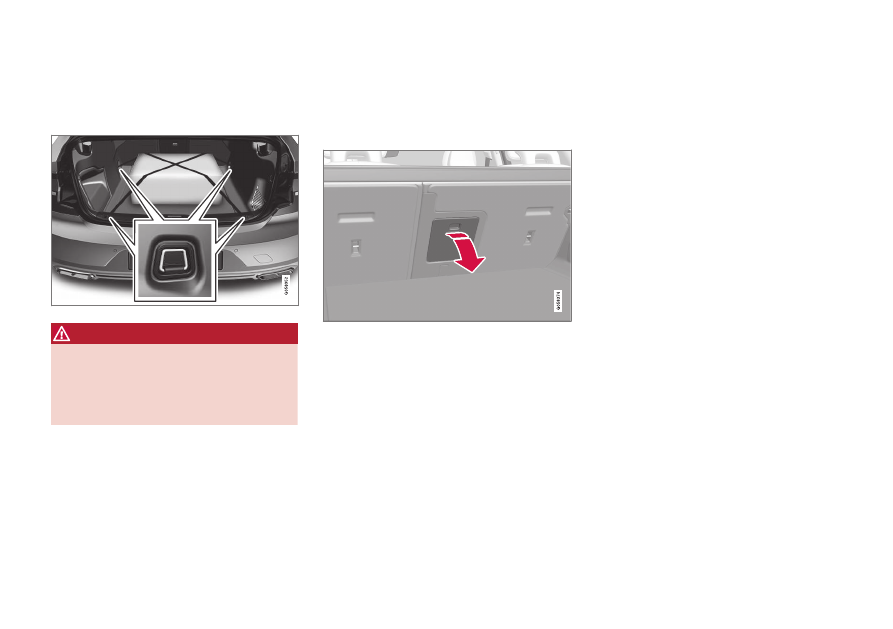
12 V electrical socket in cargo area
*
.
Related information
•
Passenger compartment interior (p. 590)
•
Using electrical sockets (p. 592)
Using electrical sockets
12 V sockets can be used for various acces-
sories designed for this, such as music play-
ers, cooler boxes and mobile phones.
For the sockets to supply current, the car's
electrical system must be set in the lowest
ignition position
I
. The sockets are then active
as long as the starter battery level does not
become too low.
If the engine is switched off and the car is
locked, the sockets are deactivated. If the
engine is switched off and the car is not
locked, or is locked with double lock tempo-
rarily deactivated, then the sockets continue to
be active for a further seven minutes.
Remember that use of the electrical socket
with the engine switched off entails a risk
of discharging the starter battery, which
can limit functionality.
Accessories that are connected to the elec-
trical sockets may be activated even when
the car's electrical system is disconnected
or if preconditioning is used. For this rea-
son, disconnect the connectors when they
are not in use in order to avoid the starter
battery being discharged.
WARNING
•
Do not use accessories with large or
heavy connectors - they can damage
the socket or come loose when driving.
•
Do not use accessories that can cause
interference to the car's radio receiver
or electrical system for example.
•
Position the accessory so that it is not
at risk of injuring the driver or passen-
gers in the event of heavy braking or
collision.
•
Keep an eye on connected accessories
as they can generate heat that can
burn passengers or the interior.
Using 12 V sockets
1. Remove the blanking plug (tunnel con-
sole) or fold down the cover (cargo area)
in front of the socket and plug in the
accessory's connector.
2. Unplug the accessory's connector and
refit the blanking plug (tunnel console) or
fold up the cover (cargo area) when the
socket is not in use or if the socket is left
unattended.
Maximum socket output is 120 W (10 A)
per socket.
-------------------------------------------------------------------------------------------------------------------------------------------------------------
LOADING, STORAGE AND PASSENGER COMPARTMENT
}}
* Option/accessory.
593
Related information
•
•
Passenger compartment interior (p. 590)
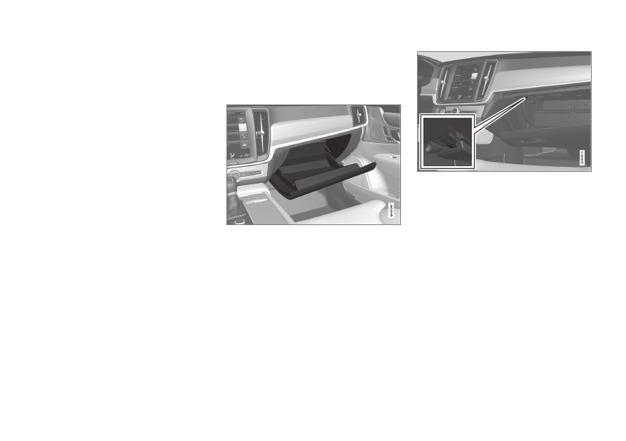
Using the glovebox
The glovebox is located on the passenger
side. The printed owner's manual and maps
can be kept in the glovebox, for example.
There is also space for a pen and card holder.
Locking and unlocking the glovebox
*
The glovebox can be locked, e.g. when the car
is taken in for service, left at a hotel or similar.
The glovebox can only be locked/unlocked
with the accompanying key.
The key's designated storage space. The figure is
schematic - the design may vary.
-------------------------------------------------------------------------------------------------------------------------------------------------------------
||
LOADING, STORAGE AND PASSENGER COMPARTMENT
* Option/accessory.
594
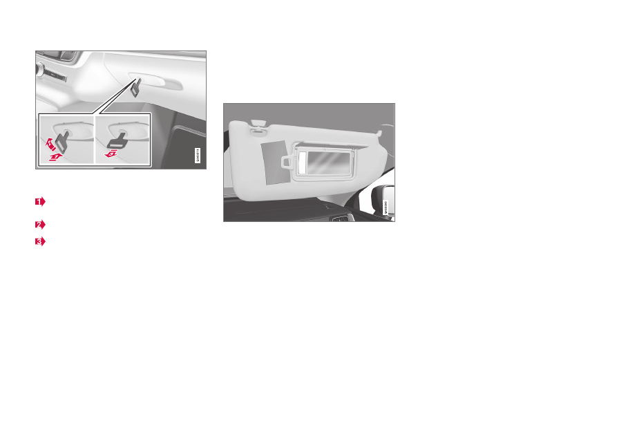
The figure is schematic - the design may vary.
Locking the glovebox:
Insert the key in the glovebox lock cylin-
der.
Turn the key 90 degrees clockwise.
Pull out the key.
–
Unlock by carrying this out in reverse
order.
Related information
•
Passenger compartment interior (p. 590)
•
Sun visors
There are sun visors in the roof in front of the
driver seat and the front seat passenger seat
which can be folded down and angled out to
the side when necessary.
The figure is schematic - the design may vary.
The mirror lighting
*
is switched on automati-
cally when the guard is lifted up.
The mirror frame incorporates a holder for e.g.
cards or tickets.
Related information
•
Passenger compartment interior (p. 590)
Cargo area
Inside the car's cargo area, it is possible to
secure the load so that it stays in place while
driving.
With folding
*
backrests in the rear seat, the
cargo area can be made more spacious. There
are load retaining eyelets and bag holders
available for holding the load securely in place.
If the car is equipped with a spare wheel then
this is attached on the cargo area floor. The
car's towing eye and puncture repair kit are
stored under the cargo area floor.
Related information
•
Recommendations for loading (p. 595)
•
•
-------------------------------------------------------------------------------------------------------------------------------------------------------------
LOADING, STORAGE AND PASSENGER COMPARTMENT
* Option/accessory.
595
Recommendations for loading
There are a number of things that are impor-
tant to bear in mind when loading the car.
Payload depends on the car's kerb weight. The
total of the weight of the passengers and all
accessories reduces the car's payload by a
corresponding weight.
WARNING
The car’s driving properties change
depending on the weight and positioning
of the load.
Loading in the cargo area
Good things to remember when loading:
•
Position the load firmly against the rear
seat's backrest.
•
Heavy objects should be placed as low as
possible. Avoid placing heavy loads on
lowered backrests.
•
Cover sharp edges with something soft to
avoid damaging the upholstery.
•
Secure all loads to the load retaining eye-
lets with straps or web lashings.
WARNING
A loose object weighing 20 kg (44 pounds)
can, in a frontal collision at a speed of
50 km/h (30 mph) carry the impact of an
item weighing 1000 kg (2200 pounds).
WARNING
Leave 10 cm (4 inches) space between the
load and the side windows if the car is loa-
ded to above the top edge of the door win-
dows. Otherwise, the intended protection
of the inflatable curtain, which is concealed
in the headlining, may be compromised.
WARNING
Always secure the load. During heavy brak-
ing the load may otherwise shift, causing
injury to the car's occupants.
Cover sharp edges and sharp corners with
something soft.
Switch off the engine and apply the park-
ing brake when loading/unloading long
items. Otherwise you may accidentally
knock the gear lever or gear selector with
the load into a drive position - and the car
could then move off.
Increasing the space in the cargo area
To expand the cargo area and simplify loading,
the rear seat's backrest can be lowered
*
. Note
that objects must not prevent the function of
the WHIPS system for the front seats if any of
the rear seat's backrests is folded down.
A through-load hatch
*
in the rear seat can be
folded down for carrying long and narrow
loads.
Related information
•
Load retaining eyelets (p. 597)
•
Lowering the backrests in the rear seat
•
Through-load hatch in the rear seat
•
Roof load and loading on load carriers
(p. 596)
•
•
-------------------------------------------------------------------------------------------------------------------------------------------------------------
LOADING, STORAGE AND PASSENGER COMPARTMENT
596
Roof load and loading on load
carriers
For loading on the car's roof, the load carriers
that Volvo have developed are recommended.
This is in order to avoid damage to the car and
in order to achieve the maximum possible
safety during a journey. Volvo's load carriers
are available for purchase at authorised Volvo
retailers.
Carefully follow the installation instructions
supplied with the carriers.
•
Distribute the load evenly over the load
carriers. Put the heaviest objects at the
bottom.
•
Check periodically that the load carriers
and load are properly secured. Lash the
load securely with retaining straps.
•
If the load is longer than the car at the
front, e.g. a canoe or kayak, fit the towing
eye to its front socket and attach the bun-
gee to this.
•
The size of the area exposed to the wind,
and therefore fuel consumption, increase
with the size of the load.
•
Drive gently. Avoid quick acceleration,
heavy braking and hard cornering.
WARNING
The car's centre of gravity and driving cha-
racteristics are altered by roof loads.
Follow the car's specifications with regard
to weights and maximum permitted load.
Related information
•
Recommendations for loading (p. 595)
•
Bag hooks
Bag hooks keep carrier bags in place and pre-
vent them from overturning and spreading
their contents across the cargo area.
Along the sides
There is a bag hook in the side panel on each
side of the cargo area.
The bag hooks may be loaded with a maxi-
mum of 5 kg (11 lbs).
Related information
•
Recommendations for loading (p. 595)
•
-------------------------------------------------------------------------------------------------------------------------------------------------------------
LOADING, STORAGE AND PASSENGER COMPARTMENT
* Option/accessory.
597
Load retaining eyelets
Use the load retaining eyelets to attach
straps in order to anchor items in the cargo
area.
WARNING
Hard, sharp and/or heavy objects which
protrude may cause injury under violent
braking.
Always secure large and heavy objects
with a seatbelt or cargo retaining straps.
Related information
•
Recommendations for loading (p. 595)
•
Through-load hatch in the rear
seat
*
The hatch in the rear seat's backrest can be
opened to transport long narrow items, e.g.
skis.
The figure is schematic - parts may vary depending
on car model.
1. In the cargo area, grip the hatch's handle
and fold down the hatch.
2. Fold forward the armrest in the rear seat.
If the private locking function is used then the
through-load hatch must be closed.
Related information
•
Recommendations for loading (p. 595)
•
•
Load retaining eyelets (p. 597)
First aid kit
*
The first aid kit contains first aid equipment.
Store the first aid kit in an appropriate place in
the cargo area, e.g. in the space on the right-
hand side. The first aid kit has Velcro straps
and can be attached directly to the panel.
Related information
•
-------------------------------------------------------------------------------------------------------------------------------------------------------------
LOADING, STORAGE AND PASSENGER COMPARTMENT
598
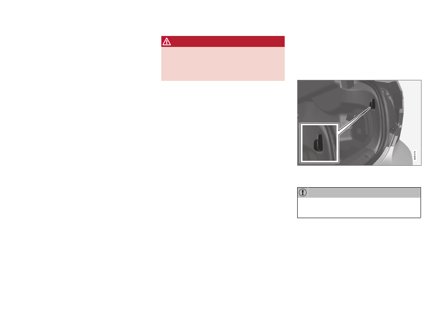
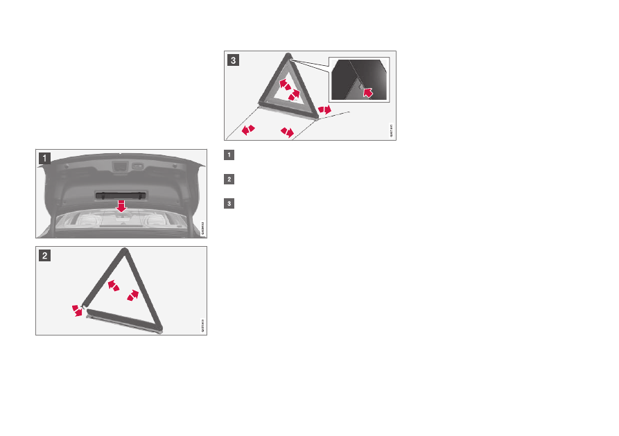
Warning triangle
Use the warning triangle to warn other road
users if the car is stationary in traffic.
Also activate the hazard warning flashers.
Storage spaces
The warning triangle is fitted with two clips on
the inside of the boot lid.
Folding up the warning triangle
Remove the warning triangle's case by
opening both latches.
Remove the warning triangle from the
case, unfold it and put the ends together.
Fold out the warning triangle's support
legs.
Follow the regulations for the use of a warning
triangle. Position the warning triangle in a suit-
able place with regard to traffic.
Replace the warning triangle with case on the
inside of the boot lid after use.
Related information
•
•
-------------------------------------------------------------------------------------------------------------------------------------------------------------
MAINTENANCE AND SERVICE
600
Volvo service programme
To keep the car as safe and reliable as possi-
ble, follow the Volvo service programme as
specified in the Service and Warranty Book-
let.
Volvo recommends engaging an authorised
Volvo workshop to perform the service and
maintenance work. Volvo workshops have the
personnel, special tools and service literature
that can provide the highest quality of service.
For the Volvo warranty to apply, check and
follow the instructions in the Service and
Warranty Booklet.
Service and repair
Service the car regularly. Follow Volvo's rec-
ommended service intervals.
If inspection and repair are required then only
an authorised Volvo workshop may carry out
the work.
WARNING
Do not carry out any repairs of your own on
this vehicle. Electrical cables and/or com-
ponents that have detached must only be
rectified by an authorised workshop - an
authorised Volvo workshop is recom-
mended.
Charging cable with control unit
Do not modify the control unit in any way.
Related information
•
•
Book service and repair (p. 603)
•
Connection of equipment to the car's
diagnostic socket (p. 40)
•
Servicing the climate control system
(p. 608)
•
Brake system maintenance (p. 454)
•
Engine compartment overview (p. 610)
Data transfer between car and
workshop via Wi-Fi
Volvo's workshops have a specific Wi-Fi net-
work for data transfer between your car and
the workshop. Your workshop visit will be
simpler and more efficient when the transfer
of diagnostic information and software can
take place via the workshop's network.
During a workshop visit, your service techni-
cian may want to connect your car to the
workshop's network via Wi-Fi to perform
fault-tracing and software download. For this
type of communication, the car only connects
to a workshop's network. It is not possible to
connect the car to another Wi-Fi network,
such as at home, in the same way as to a
workshop's network.
Connection with the remote control
key
Connection is normally handled by the service
technician who then uses the remote control
key buttons. That's why it's important to take
a key with buttons with you for the workshop
visit. Press three times on the lock button on
the remote control key to connect the car to
the workshop's network via Wi-Fi.
When the car is connected to a Wi-Fi net-
work, the
symbol appears in the centre
display.
-------------------------------------------------------------------------------------------------------------------------------------------------------------
MAINTENANCE AND SERVICE
}}
* Option/accessory.
601
WARNING
The car must not be driven when con-
nected to the workshop's networks and
systems.
Related information
•
Managing system updates via the Down-
load Centre (p. 601)
•
Book service and repair (p. 603)
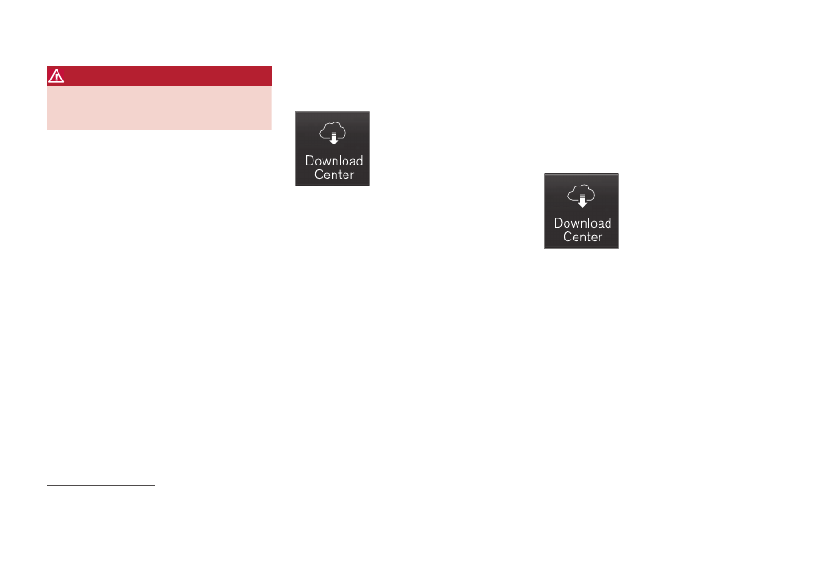
Download Center
Several of the car's systems can be updated
from the centre display with an online car
1
.
The
Download Centre
app is
started from app view in the
centre display and enables:
•
searching for and updating system soft-
ware
•
updating map data for Sensus Navigation
*
•
downloading, updating and uninstalling
apps.
Related information
•
Managing system updates via the Down-
load Centre (p. 601)
•
•
•
•
•
Navigating in the centre display's views
(p. 113)
Managing system updates via the
Download Centre
Functions for online car and infotainment can
be updated via the Download Centre.
Updates can be made one at a time or all at
once.
Searching for update
If an update is available, the
message
New software
updates available See
Download Center
is shown
in the centre display's status
bar.
For system updates to be possible, the car
must be connected to the Internet
2
.
–
Go to
Download Centre
in the centre dis-
play's app view.
> If no search has been performed since
the last time the infotainment system
was started, a search is performed. No
search is performed if a software instal-
lation is in progress.
A number on
System updates
shows
how many updates are available. One
tap shows a list of the updates that can
be installed in the car.
1
Data is transferred (data traffic) when using the Internet, and this may involve a cost.
2
Data is transferred (data traffic) when using the Internet, and this may involve a cost.
-------------------------------------------------------------------------------------------------------------------------------------------------------------
Нет комментариевНе стесняйтесь поделиться с нами вашим ценным мнением.
Текст