Toyota Sequoia (2005). Manual — part 544
I28313
R2
R3
R19
–
DIAGNOSTICS
AUDIO SYSTEM
DI–1971
2165
*1: w/ Rear seat entertainment system
*2: w/ Rear seat audio system
2.
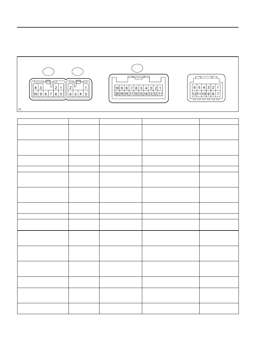
RADIO RECEIVER ASSY (BUILT–IN TYPE AMPLIFIER)
Symbols (Terminal No.)
Wiring Color
Terminal Description
Condition
Specification
FR+ (R2–1) – GND (R2–7)
LG – BR
Sound signal (Front Right)
Audio system is playing
A waveform synchro-
nized with sounds is
output
FL+ (R2–2) – GND (R2–7)
P – BR
Sound signal (Front Left)
Audio system is playing
A waveform synchro-
nized with sounds is
output
ACC+B (R2–3) – GND (R2–7)
GR – BR
Accessory (ON)
Turn ignition switch to OFF
→
ACC
Below 1 V
→
10 to 14 V
BU+B (R2–4) – GND (R2–7)
L–Y – BR
Battery
Always
10 to 14 V
FR– (R2–5) – GND (R2–7)
L – BR
Sound signal (Front Right)
Audio system is playing
A waveform synchro-
nized with sounds is
output
FL– (R2–6) – GND (R2–7)
V – BR
Sound signal (Front Left)
Audio system is playing
A waveform synchro-
nized with sounds is
output
GND (R2–7) – Body ground
BR –
Body ground
Ground
Always
Below 1 V
ANT+B (R2–8) – GND (R2–7)
B–R – BR
Power source of antenna
Radio switch ON and AM or FM
10 to 14 V
ILL+ (R2–10) – GND (R2–7)
G – BR
Illumination (rheostat) sig-
nal
Light control switch OFF
→
TAIL or
HEAD
Below 1 V
→
10 to 14 V
RR+ (R3–1) – GND (R2–7)
R – BR
Sound signal (Rear Right)
Audio system is playing
A waveform synchro-
nized with sounds is
output
RL+ (R3–2) – GND (R2–7)
B – BR
Sound signal (Rear Left)
Audio system is playing
A waveform synchro-
nized with sounds is
output
RR– (R3–3) – GND (R2–7)
W – BR
Sound signal (Rear Right)
Audio system is playing
A waveform synchro-
nized with sounds is
output
ILL– (R3–5) – GND (R2–7)
W–G – BR
Illumination (rheostat) sig-
nal
Light control switch OFF
→
TAIL or
HEAD
Below 1 V
→
10 to 14 V
RL– (R3–6) – GND (R2–7)
Y – BR
Sound signal (Rear Left)
Audio system is playing
A waveform synchro-
nized with sounds is
output
GND (R19–6) – GND (R2–7)
BR–W – BR
Steering pad switch
ground
Always
Below 1 V
I28722
S10
S9
DI–1972
–
DIAGNOSTICS
AUDIO SYSTEM
2166
SW1 (R19–7) – GND (R2–70)
LG–R – BR
Steering pad switch signal
Steering pad switch not operating.
→
SEEK+ switch push
→
SEEK– switch push
→
VOL+ switch push
→
VOL– switch push
4 V or more
→
Approx. 0.5 V
→
Approx. 0.9 V
→
Approx. 2.0 V
→
Approx. 3.4 V
SW2 (R19–8) – GND (R2–7)
GR–R – BR
Steering pad switch signal
Steering pad switch not operating
→
MODE switch push
4 V or more
→
Below 2.5 V
3.
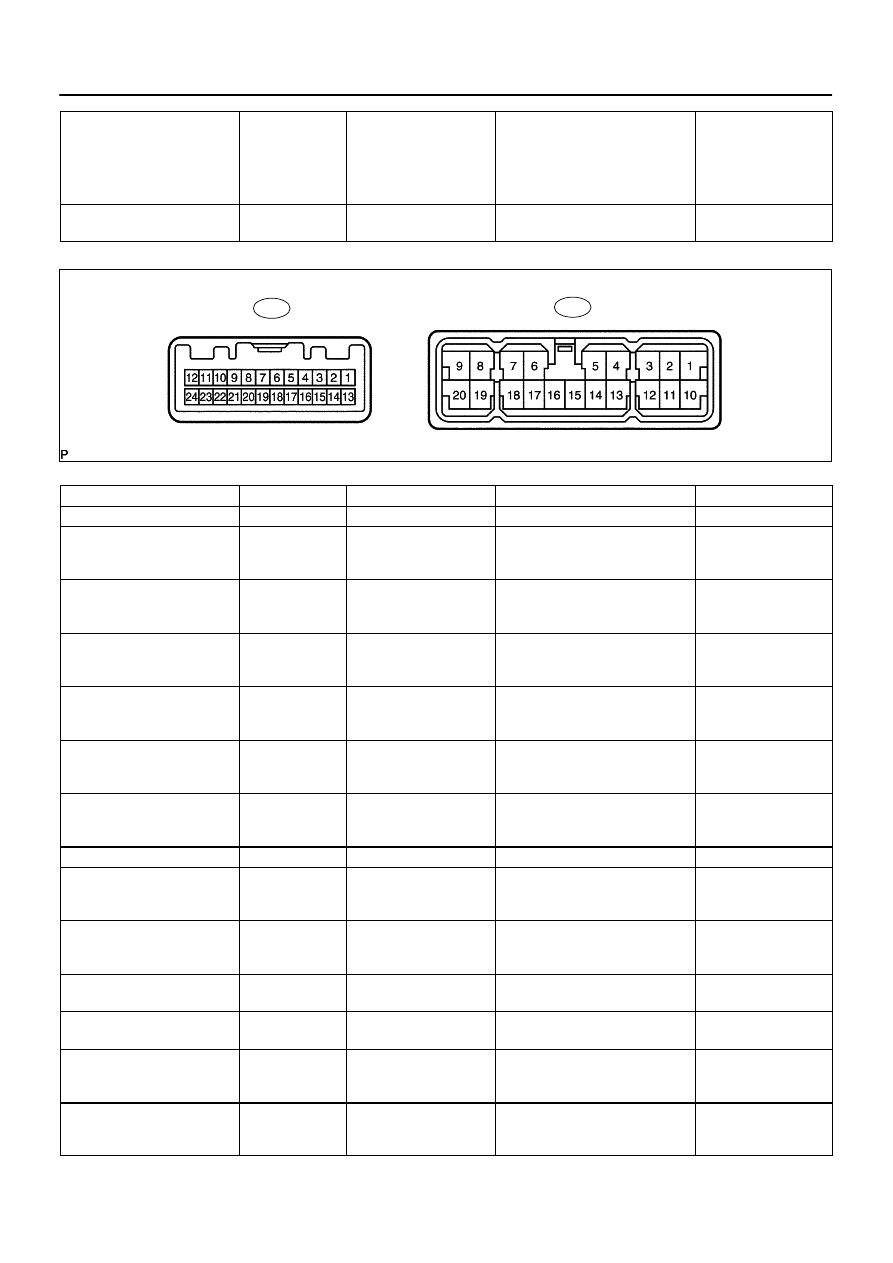
STEREO COMPONENT AMPLIFIER ASSY
Symbols (Terminal No.)
Wiring Color
Terminal Description
Condition
Specification
B+ (S9–1) – E (S9–16)
L–W – BR
Battery
Always
10 to 14 V
RL+ (S9–4) – E (S9–16)
B – BR
Sound signal (Rear Left)
Audio system is playing
A waveform synchro-
nized with sounds is
output
RR+ (S9–5) – E (S9–16)
R – BR
Sound signal (Rear Right)
Audio system is playing
A waveform synchro-
nized with sounds is
output
FL+ (S9–2) – E (S9–16)
P – BR
Sound signal (Front Left)
Audio system is playing
A waveform synchro-
nized with sounds is
output
FR+ (S9–3) – E (S9–16)
LG – BR
Sound signal (Front Right)
Audio system is playing
A waveform synchro-
nized with sounds is
output
WFL+ (S9–6) –
E (S9–16)
L–W – BR
Sound signal (Front Left)
Audio system is playing
A waveform synchro-
nized with sounds is
output
WFR+ (S9–7) –
E (S9–16)
R – BR
Sound signal (Front Right)
Audio system is playing
A waveform synchro-
nized with sounds is
output
B2+ (S9–10) – E (S9–16)
L–W – BR
Battery
Always
10 to 14 V
RL– (S9–13) – E (S9–16)
Y – BR
Sound signal (Rear Left)
Audio system is playing
A waveform synchro-
nized with sounds is
output
RR– (S9–14) – E (S9–16)
W – BR
Sound signal (Rear Right)
Audio system is playing
A waveform synchro-
nized with sounds is
output
GND (S9–15) – Body ground
BR –
Body ground
Ground
Always
Below 1 V
E (S9–16) – Body ground
BR –
Body ground
Ground
Always
Below 1 V
FL– (S9–11) – E (S9–16)
V – BR
Sound signal (Front Left)
Audio system is playing
A waveform synchro-
nized with sounds is
output
FR– (S9–12) – E (S9–16)
L – BR
Sound signal (Front Right)
Audio system is playing
A waveform synchro-
nized with sounds is
output

–
DIAGNOSTICS
AUDIO SYSTEM
DI–1973
2167
WFL– (S9–17) –
E (S9–16)
G – BR
Sound signal (Front Left)
Audio system is playing
A waveform synchro-
nized with sounds is
output
WFR– (S9–18) –
E (S9–16)
Y – BR
Sound signal (Front Right)
Audio system is playing
A waveform synchro-
nized with sounds is
output
MUTE (S10–1) – E (S9–16)
R–W – BR
Mute signal from radio
receiver
Audio system is sounding
→
changing mode
Above 3.5 V
→
Below 1 V
L– (S10–2) – E (S9–16)
R – BR
Sound signal from radio
receiver (Left)
Audio system is playing
A waveform synchro-
nized with sounds is
output
L+ (S10–3) – E (S9–16)
B – BR
Sound signal from radio
receiver (Left)
Audio system is playing
A waveform synchro-
nized with sounds is
output
R– (S10–4) – E (S9–16)
G – BR
Sound signal from radio
receiver (Right)
Audio system is playing
A waveform synchro-
nized with sounds is
output
R+ (S10–5) – E (S9–16)
W – BR
Sound signal from radio
receiver (Right)
Audio system is playing
A waveform synchro-
nized with sounds is
output
SGND (S10–6) – Body ground
Shielded –
Body ground
Ground
Always
Below 1 V
ACC (S10–12) – E (S9–16)
GR – BR
Accessory (ON)
Turn ignition switch OFF
→
ACC
Below 1 V
→
10 to 14 V
TX– (S10–19) – E (S9–16)
P – BR
AVC–LAN
communication signal
Turn ignition switch to ACC
2 to 3 V
TX+ (S10–20) – E (S9–16)
V – BR
AVC–LAN
communication signal
Turn ignition switch to ACC
2 to 3 V
4.
MULTI–DISPLAY CONTROLLER ASSY
See page
5.
REAR SEAT AUDIO CONTROLLER
See page
DID9S–01
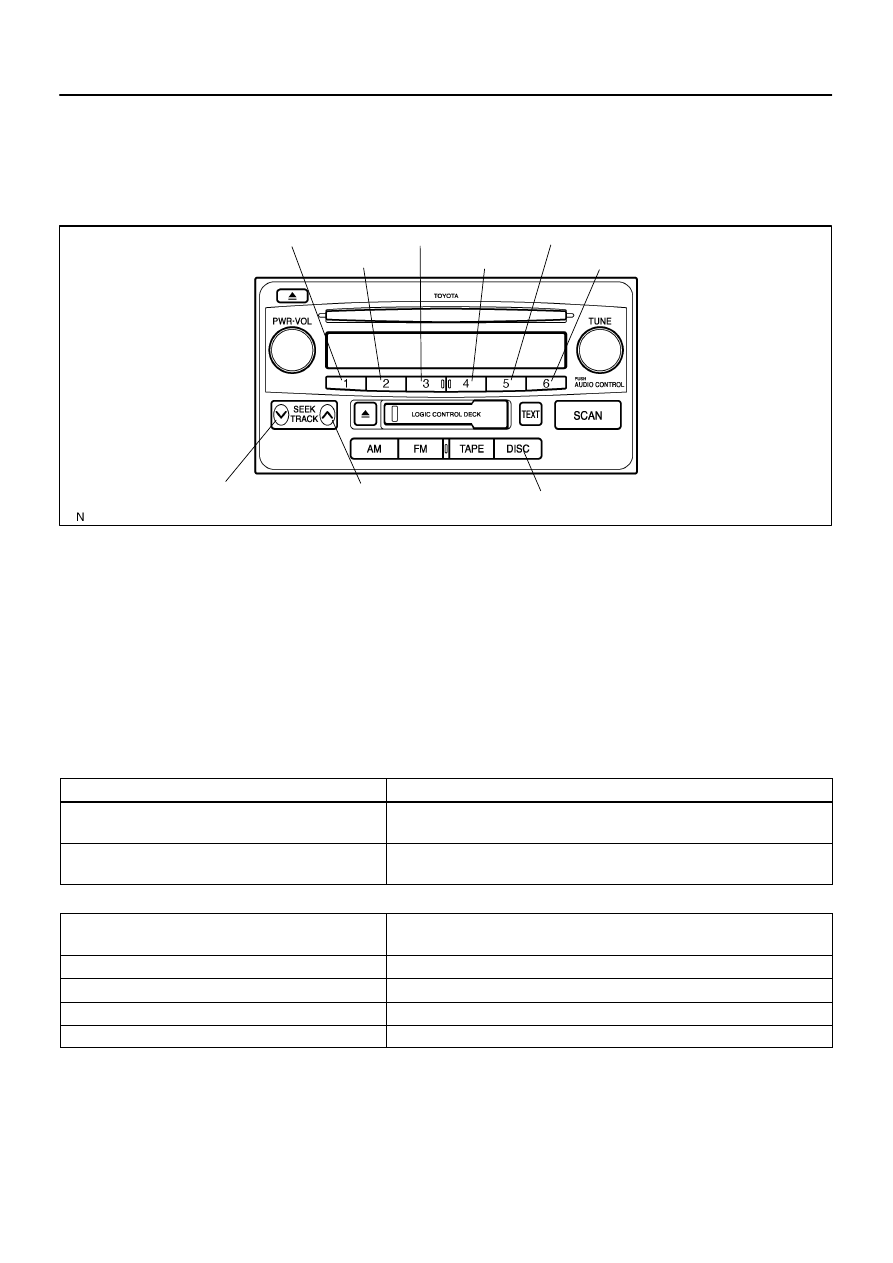
I24383
”1ch” Switch
”SEEK TRACK”
DOWN Switch
”SEEK TRACK”
UP Switch
”DISC” Switch
”2ch” Switch
”3ch” Switch
”4ch” Switch
”5ch” Switch
”6ch” Switch
DI–1974
–
DIAGNOSTICS
AUDIO SYSTEM
2168
DTC CHECK / CLEAR
1.
DIAGNOSTIC CHECK
(a)
Starting Diagnostic Mode (All elements come on during the SW check mode).
(1)
Turn off the audio system and turn the ignition switch to the ACC position. While pressing the
preset switches ”1” and ”6” at the same time, press the ”DISC” 3 times.
(2)
Reference:
When the system enters the Diagnosis Mode, a beep sound is emitted 3 times and all the
elements come on during the SW check mode.
It takes about 40 seconds to complete the check.
Turn all the elements in the LCD on.
When pressing the switch, confirm beep sound is emitted.
(b)
Service Check Screen.
(1)
Press the ”SEEK TRACK” switch to enter the ”Service Check Screen”.
(2)
In the service check mode, the system check and the diagnostic memory check are performed,
and the check results are displayed in ascending order of the component codes (physical ad-
dress.)
Terms
Meaning
Component code
(Physical address)
Three–digit code (In hexadecimal) given to each device comprising AVC–LAN.
Corresponding to its function, individual symbol is provided.
Logical address
Two–digit code (In hexadecimal) given to each function and device unit in each
device comprising AVC–LAN.
Code No. (physical address) List
Code No.
(physical address)
Equipment name
190
Radio receiver assy (Audio head unit)
440
Stereo component amplifier assy
1F6
Multi–display controller (RSE ECU)
1F4
Rear seat audio controller
(c)
Finishing Diagnostic Mode.
Press the ”DISC” for 2 seconds or more, or turn the ignition switch off.
Нет комментариевНе стесняйтесь поделиться с нами вашим ценным мнением.
Текст