Toyota Sequoia (2005). Manual — part 101
A23476
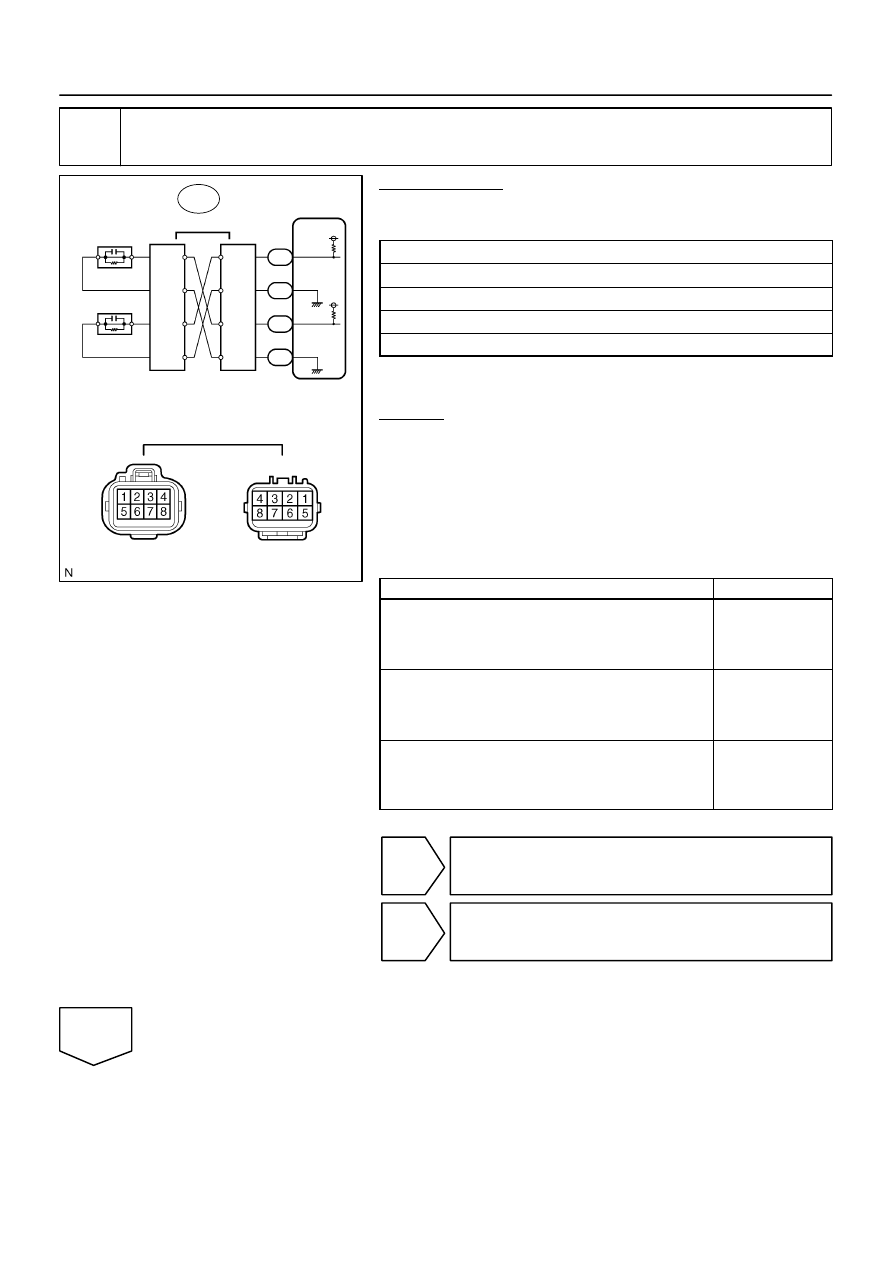
ECM
EB4
EB4
Female
Connector
Male
Connector
Knock Sensor
8
3
4
7
8
3
4
7
2
1
2
1
E7
E7
E7
E7
28
21
20
KNK1
EKNK
KNK2
EKN2
29
–
DIAGNOSTICS
ENGINE
DI–207
401
1
Connect hand–held tester, and check knock sensor circuit.
PREPARATION:
(a)
Disconnect the EB4 connector.
(b)
Using lead wires, connect the EB4 connectors as follows.
Male Connector – Female Connector
Terminal 4 – Terminal 8
Terminal 3 – Terminal 7
Terminal 8 – Terminal 4
Terminal 7 – Terminal 3
(c)
Warm up the engine.
(d)
Run the engine at 3,000 rpm for 10 seconds or more.
CHECK:
(a)
Connect the hand–held tester to the DLC3.
(b)
Turn the ignition switch to ON and turn the hand–held tes-
ter ON.
(c)
Select the item: DIAGNOSIS / ENHANCED OBD II / DTC
INFO / CURRENT CODES.
(d)
Read DTCs.
Result :
Display
Proceed to
DTCs same as when vehicle brought in
P0325, P0327, P0328
→
P0325, P0327, P0328
or
P0330, P0332, P0333
→
P0330, P0332, P0333
A
DTC different from when vehicle brought in
P0325
→
P0330
or
P0330
→
P0325
B
DTCs different from when vehicle brought in
P0327, P0328
→
P0332, P0333
or
P0332, P0333
→
P0327, P0328
C
(e)
Reconnect the EB4 connector.
B
Go to step 4.
C
Go to step 5.
A
B17411
KNK1
KNK2
EKN2
EKNK
E7
DI–208
–
DIAGNOSTICS
ENGINE
402
2
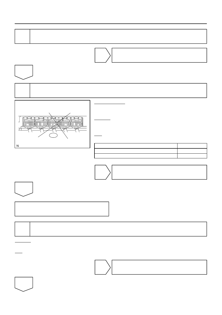
Check for open and short in harness and connector between EB4 connector and
ECM (See page
).
NG
Repair or replace harness or connector.
OK
3
Measure voltage between terminals KNK1 and EKNK, KNK2 and EKN2 of ECM.
PREPARATION:
(a)
Disconnect the E7 ECM connector.
(b)
Turn the ignition switch to ON.
CHECK:
(a)
Measure the voltage between the specified ECM termi-
nals.
OK:
Standard:
Tester Connection
Specified Condition
KNK1 (E7–29) – EKNK (E7–28)
4.5 to 5.5 V
KNK2 (E7–21) – EKN2 (E7–20)
4.5 to 5.5 V
(b)
Reconnect the ECM connector.
NG
Replace ECM (See page
OK
Check for intermittent problems
(See page
4
Check knock sensor installation.
CHECK:
Check the knock sensor installation.
OK:
Torque: 20 N
⋅
m (204 kgf
⋅
cm, 15 ft
⋅
lbf)
NG
Tighten the sensor.
OK
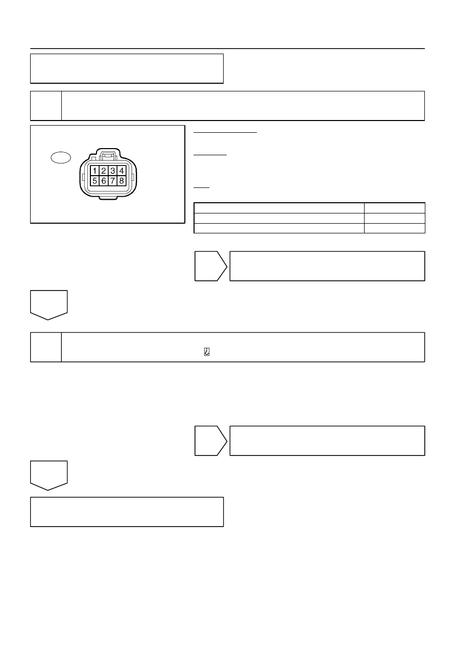
A23513
Male Connector
EB4
Wire Harness Side:
Front View
–
DIAGNOSTICS
ENGINE
DI–209
403
Replace knock sensor (See page
5
Check knock sensor.
PREPARATION:
(a)
Disconnect the EB4 connector.
CHECK:
(a)
Check the resistance between the terminals of the EB4
male connector.
OK:
Standard:
Tester Connection
Specified Condition
EB4 male connector 3 –4
120 to 280 k
Ω
EB4 male connector 7 – 8
120 to 280 k
Ω
(b)
Reconnect the EB4 connector.
OK
Check for intermittent problems
(See page
NG
6
Check for open and short in harness and connector between EB4 connector and
knock sensor (See page
HINT:
If DTC P0327 or P0328 has changed to P0332 or P0333, check the knock sensor circuit on the right
bank side.
If DTC P0332 or P0333 has changed to P0327 or P0328, check the knock sensor circuit on the left
bank side.
NG
Repair or replace harness or connector.
OK
Replace knock sensor.
FI7059
FI7060
A00069
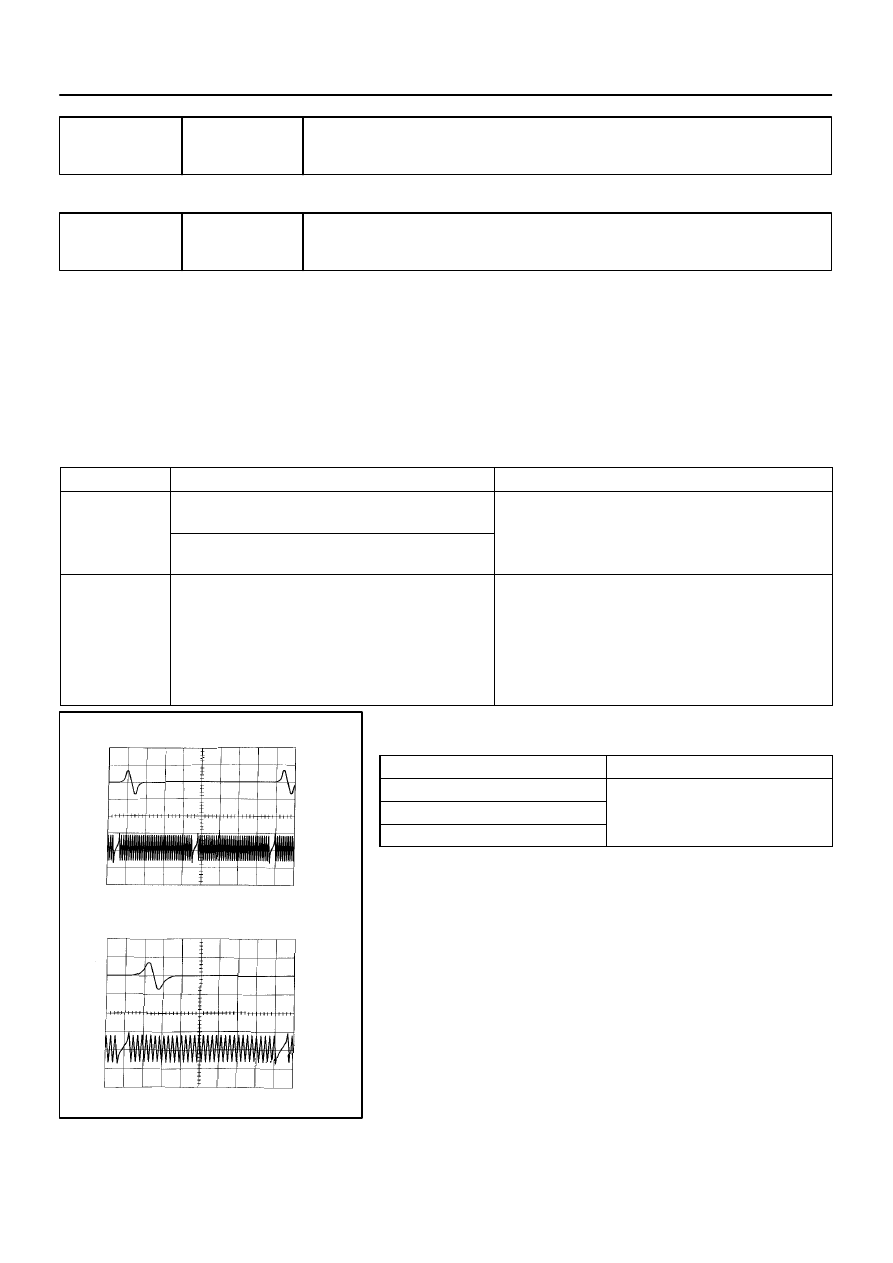
G2 and NE Signal Waveforms
20 msec./Division (Idling)
10 msec./Division (Idling)
5 V
/Division
G2
NE
5 V
/Division
G2
NE
DI–210
–
DIAGNOSTICS
ENGINE
404
DTC
P0335
Crankshaft Position Sensor ”A” Circuit
DTC
P0339
Crankshaft Position Sensor ”A” Circuit In-
termittent
CIRCUIT DESCRIPTION
The crankshaft position sensor system consists of a crankshaft position sensor plate and a pick–up coil.
The sensor plate has 32 teeth and is installed on the crankshaft. The pick–up coil is made of an iron core
and magnet. The sensor plate rotates and as each tooth passes through the pick–up coil, a pulse signal is
created. The pick–up coil generates 32 signals for each engine revolution. Based on these signals, the ECM
calculates the crankshaft position and engine RPM. Using these calculations, the fuel injection time and igni-
tion timing are controlled.
DTC No.
DTC Detecting Condition
Trouble Area
P0335
No crankshaft position sensor signal to ECM during crank-
ing (2 trip detection logic)
Open or short in crankshaft position sensor circuit
Crankshaft position sensor
P0335
No crankshaft position sensor signal to ECM with engine
speed 450 rpm or more (1 trip detection logic)
Crankshaft osition sensor
Signal plate
ECM
P0339
In condition (a), (b) and (c), when no crankshaft position
sensor (NE) signal is input for 0.05 sec. or more. :
(1 trip detection logic)
(c) Engine revolution 1,000 rpm or more
(d) STA signal is OFF
(e) 3 sec. or more has lapsed after STA signal is switched
from ON to OFF.
Open or short in crankshaft position sensor circuit
Crankshaft position sensor
Signal plate
ECM
Reference: Inspection using the oscilloscope.
The correct waveform is as shown in the illustration.
Tester Connection
Specified Condition
VV1+ (E6–25) – VV1– (E6–24)
VV2+ (E6–18) – VV2– (E6–28)
Correct waveform is as shown
NE+ (E6–21) – NE– (E6–20)
Correct waveform is as shown
DID86–01
Нет комментариевНе стесняйтесь поделиться с нами вашим ценным мнением.
Текст