Toyota Sequoia (2005). Manual — part 100
S01196
S01699
30
20
10
5
3
0
20 40
0.1
1
0.3
0.2
0.5
2
60 80 100
–20
(–4)
(104) (140) (176)
(32) (68)
(212)
A21042
Ohmmeter
Acceptable
TEMPERATURE
C (
F)
RESIST
ANCE K
Ω
–
DIAGNOSTICS
ENGINE
DI–203
397
18
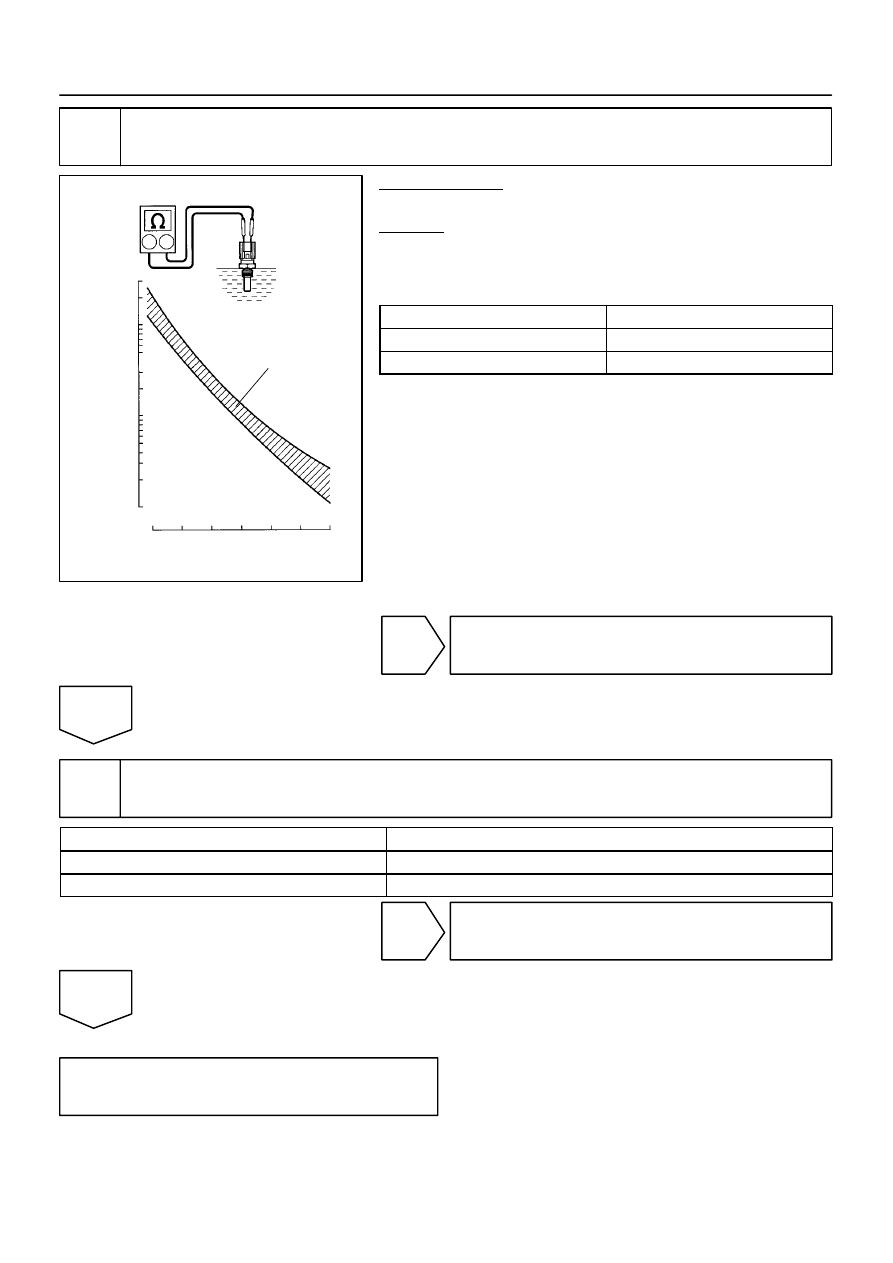
Check engine coolant temperature sensor.
PREPARATION:
Remove the engine coolant temperature sensor.
CHECK:
Measure the resistance between the terminals of the engine
coolant temperature sensor.
Resistance:
Tester Connection
Specified Condition
1 – 2
2.32 to 2.59 k
Ω
(20
C (68
F))
1 – 2
0.310 to 0.326 k
Ω
(80
C (176
F))
NOTICE:
In case of checking the engine coolant temperature sensor
in the water, be careful not to allow water to go into the ter-
minals. After checking, dry the sensor.
HINT:
Alternate procedure: Connect an ohmmeter to the installed en-
gine coolant temperature sensor and read the resistance. Use
an infrared thermometer to measure the engine temperature in
the immediate vicinity of the sensor. Compare these values to
the resistance/temperature graph. Change the engine temper-
ature (by warming up or cooling down) and repeat the test.
NG
Replace
engine coolant temperature sensor.
OK
19
Switch step by number of misfire cylinder (Refer to the result of step 4).
High misfire rate cylinder
Proceed to
1 or 2 cylinders
A
More than 3 cylinders
B
B
Go to step 5.
A
Check for intermittent problems
(See page
DI–204
–
DIAGNOSTICS
ENGINE
398
DTC
P0325
Knock Sensor 1 Circuit (Bank 1 or Single
Sensor)
DTC
P0327
Knock Sensor 1 Circuit Low Input (Bank 1 or
Single Sensor)
DTC
P0328
Knock Sensor 1 Circuit High Input (Bank 1
or Single Sensor)
DTC
P0330
Knock Sensor 2 Circuit (Bank 2)
DTC
P0332
Knock Sensor 2 Circuit Low Input (Bank 2)
DTC
P0333
Knock Sensor 2 Circuit High Input (Bank 2)
CIRCUIT DESCRIPTION
A flat type knock sensor (non–resonant type) has the structure that can detect the vibration in a wider band
of frequency from about 6 kHz to 15 kHz and has the following features.
Knock sensors are fitted on the right bank and left bank of the cylinder block to detect engine knocking.
Each knock sensor contains a piezoelectric element which generates voltage when it becomes deformed.
Generation of the voltage occurs when the cylinder block vibrates due to knocking. If engine knocking oc-
curs, the ignition timing is retarded in order to suppress the knocking.
DTC No.
DTC Detection Condition
Trouble Area
P0325
P0330
Knock sensor signal level remains at low
(1 trip detection logic)
Knock sensor 1 or 2
Knock sensor 1 or 2 (looseness)
ECM
P0327
P0332
Output voltage of the knock sensor 1 or 2 is 0.5 V or less
(1 trip detection logic)
Short in knock sensor 1 or 2 circuit
Knock sensor 1 or 2
ECM
P0328
P0333
Output voltage of the knock sensor 1 or 2 is 4.5 V or more
(1 trip detection logic)
Open in knock sensor 1 or 2 circuit
Knock sensor 1 or 2
ECM
DIDFS–01
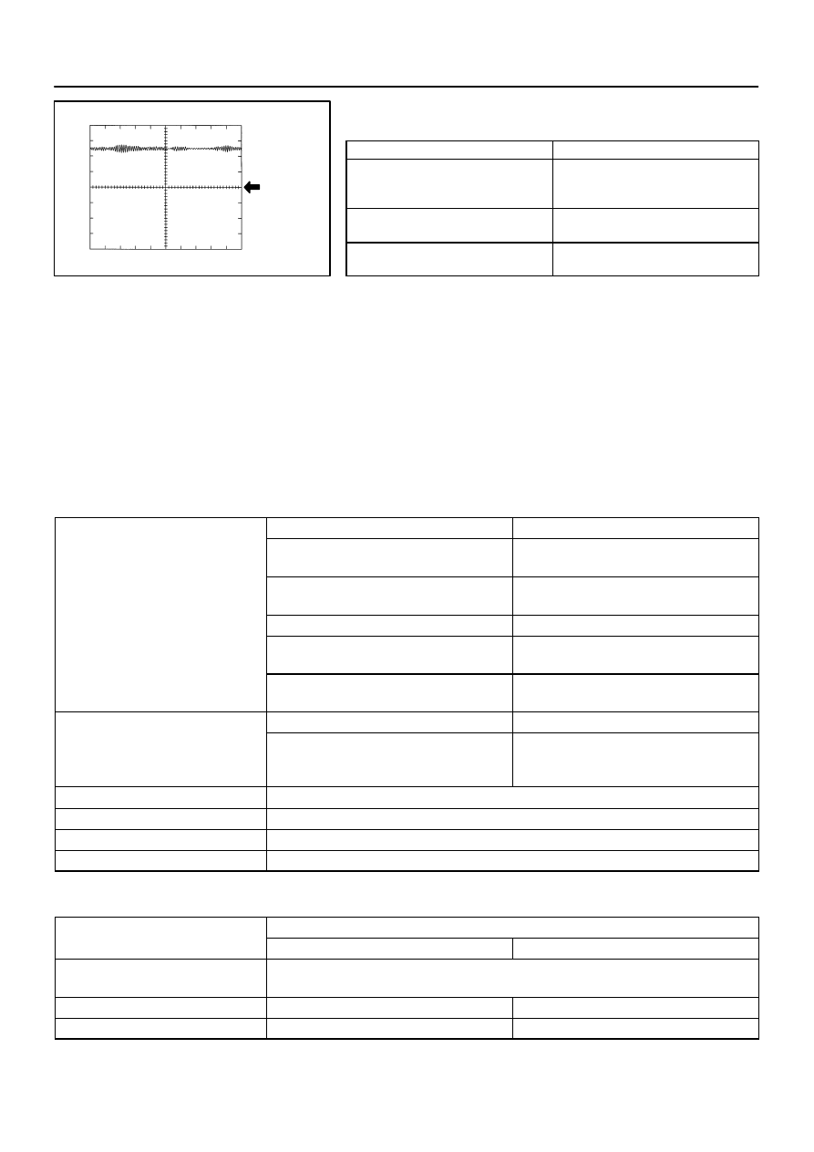
A23648
GND
1V/ DIV
KNK1 Signal Waveform
1 msec./ Division
–
DIAGNOSTICS
ENGINE
DI–205
399
Reference: Inspection using the oscilloscope.
The correct waveform is as shown.
Item
Details
Terminal
KNK1 – EKNK
or
KNK2 – EKN2
Equipment Settings
0.01 to 10 V/Division,
0.01 to 10 msec./Division
Condition
After warming up the engine,
keep the engine speed at 4,000 rpm.
MONITOR DESCRIPTION
The knock sensor located on the cylinder block detects spark knock.
When spark knock occurs, the sensor pick–up vibrates in a specific frequency range. When the ECM detects
the voltage in this frequency range, it retards the ignition timing to suppress the spark knock.
If there is a defect in the knock sensor or an open or short circuit, the voltage level will deviate outside the
normal operating range. The ECM interprets this deviation as a defect in the knock sensor and sets a DTC.
Example:
When the knock sensor voltage output is less than 0.5 V, or more than 4.5 V, and if either the condition contin-
ues for more than 3 sec.
MONITOR STRATEGY
P0325
Knock sensor (Bank 1) range check (Chattering)
P0327
Knock sensor (Bank 1) range check (Low volt-
age)
R l t d DTC
P0328
Knock sensor (Bank 1) range check (High volt-
age)
Related DTCs
P0330
Knock sensor (Bank 2) range check (Chattering)
P0327
Knock sensor (Bank 2) range check (Low volt-
age)
P0328
Knock sensor (Bank 2) range check (High volt-
age)
Main sensors/components
Knock sensor
Required sensors/components
Related sensors/components
Crankshaft position sensor, Camshaft position
sensor, Engine coolant temperature sensor,
Mass air flow meter
Frequency of operation
Continuous
Duration
1 sec.
MIL operation
Immediate
Sequence of operation
None
TYPICAL ENABLING CONDITIONS
It
Specification
Item
Minimum
Maximum
The monitor will run whenever these
DTCs are not present
See page
Battery voltage
10.5 V
–
Time after engine start
5 sec.
–
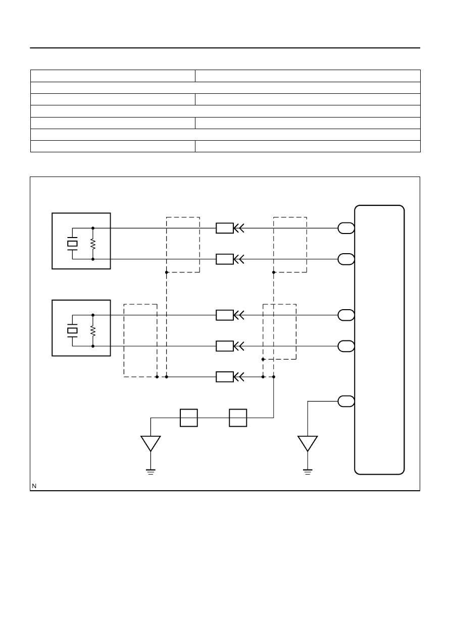
A23549
ECU
KNK1
21
E7
B
GR
4
K1
Knock Sensor 1
(Bank 1)
B
8
1
K2
Knock Sensor 2
(Bank 2)
1
20
KNK2
E7
BR
7
2
EB4
EB4
2
3
EB
EC
1
BR
BR
BR
E
(Shielded)
BR
(Shielded)
EB4
EB4
EB4
(Shielded)
(Shielded)
2
G
R
W
W
G
R
EKN2
EKNK
E1
E6
E7
E7
29
28
BR
E
D
D
J42
J/C
J42
J/C
DI–206
–
DIAGNOSTICS
ENGINE
400
TYPICAL MALFUNCTION THRESHOLDS
Detection Criteria
Threshold
Knock sensor range check (Chattering) P0325, P0330:
Knock sensor voltage
Less than 0.5 V, or more than 4.5 V
Knock sensor range check (Low voltage) P0327, P0332:
Knock sensor voltage
Less than 0.5 V
Knock sensor range check (High voltage) P0328, P0333:
Knock sensor voltage
More than 4.5 V
WIRING DIAGRAM
INSPECTION PROCEDURE
HINT:
DTC P0325, P0327 and P0328 are for the bank 1 knock sensor circuit.
DTC P0330, P0332 and P0333 are for the bank 2 knock sensor circuit.
Read freeze frame data using the hand–held tester. Freeze frame data records the engine conditions
when a malfunction is detected. When troubleshooting, freeze frame data can help determine if the
vehicle was running or stopped, if the engine was warmed up or not, if the air–fuel ratio was lean or
rich, and other data from the time the malfunction occurred.
Нет комментариевНе стесняйтесь поделиться с нами вашим ценным мнением.
Текст