Toyota Sequoia (2005). Manual — part 95
A21377
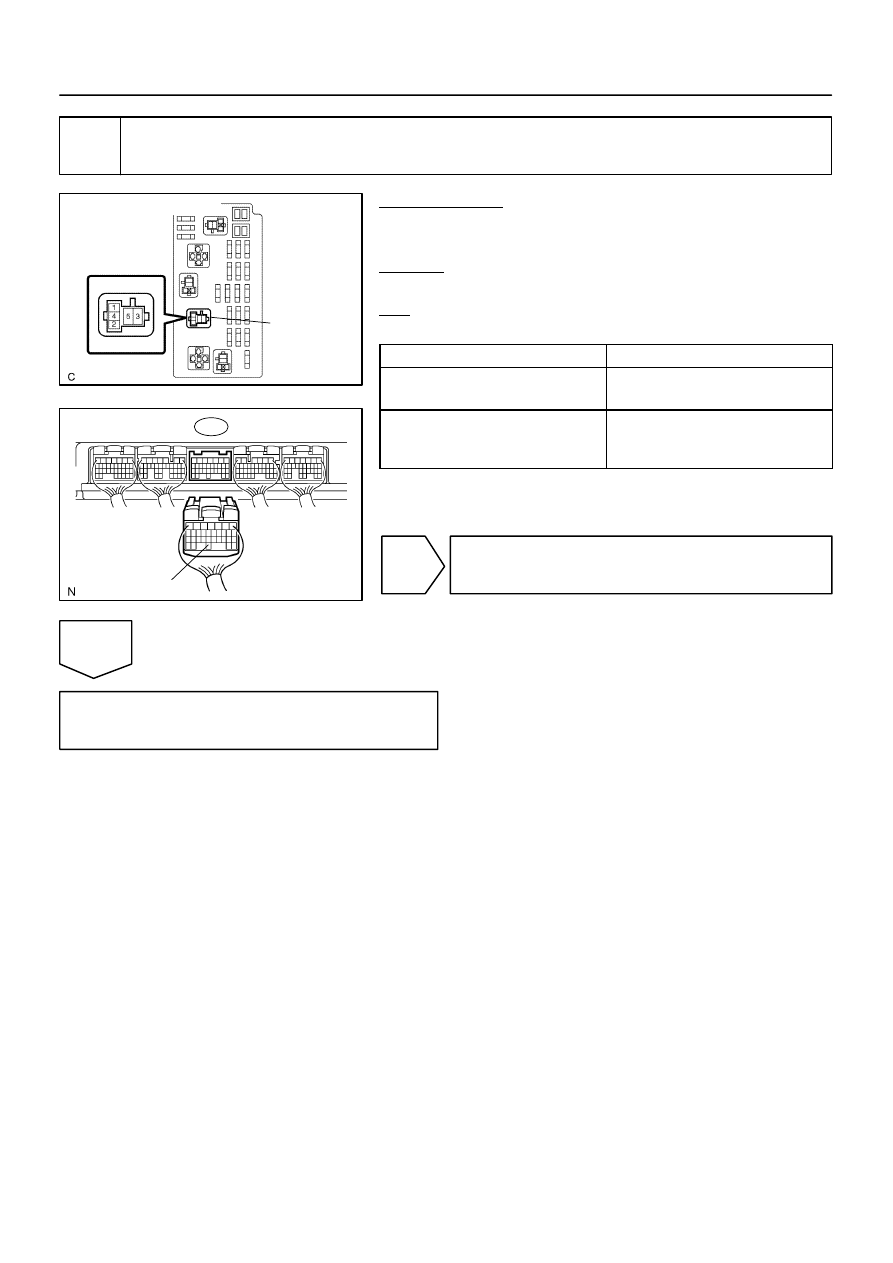
Engine Room J/B:
Fuel Pump
Relay
B17414
E6
ECM Connector
FPR
–
DIAGNOSTICS
ENGINE
DI–183
377
3
Check for open and short in harness and connector between fuel pump relay
and ECM.
PREPARATION:
(a)
Remove the fuel pump relay from the engine room J/B.
(b)
Disconnect the E6 ECM connector.
CHECK:
Measure the resistance between wire harness side connectors.
OK:
Standard:
Tester Connection
Specified Condition
Engine Room J/B (Fuel pump relay ter-
minal 1) – FPR (E6–30)
Below 1
Ω
Engine Room J/B (Fuel pump relay ter-
minal 1) or FPR (E6–30) –
Body ground
10 k
Ω
or higher
NG
Repair or replace harness or connector.
OK
Replace ECM (See page

DI–184
–
DIAGNOSTICS
ENGINE
378
DTC
P0300
Random/Multiple Cylinder Misfire Detected
DTC
P0301
Cylinder 1 Misfire Detected
DTC
P0302
Cylinder 2 Misfire Detected
DTC
P0303
Cylinder 3 Misfire Detected
DTC
P0304
Cylinder 4 Misfire Detected
DTC
P0305
Cylinder 5 Misfire Detected
DTC
P0306
Cylinder 6 Misfire Detected
DTC
P0307
Cylinder 7 Misfire Detected
DTC
P0308
Cylinder 8 Misfire Detected
CIRCUIT DESCRIPTION
When a misfire occurs in the engine, hydrocarbons (HC) enter the exhaust in high concentrations. If this HC
concentration is high enough, there could be an increase in exhaust emission levels. High concentrations
of HC can also cause the temperature of the catalyst to increase, possibly damaging the catalyst. To prevent
this increase in emissions and limit the possibility of thermal damage, the ECM monitors the misfire rate.
When the temperature of the catalyst reaches a point of thermal degradation, the ECM will blink the MIL.
For monitoring misfire, the ECM uses both the camshaft position sensor and the crankshaft position sensor.
The camshaft position sensor is used to identify misfiring cylinders and the crankshaft position sensor is used
to measure variations in the crankshaft rotation speed. The misfire counter increments when crankshaft rota-
tion speed variations exceed threshold values.
If the misfiring rate exceeds the threshold value, which could cause emissions deterioration, the ECM illumi-
nates the MIL.
DID85–01
A20646
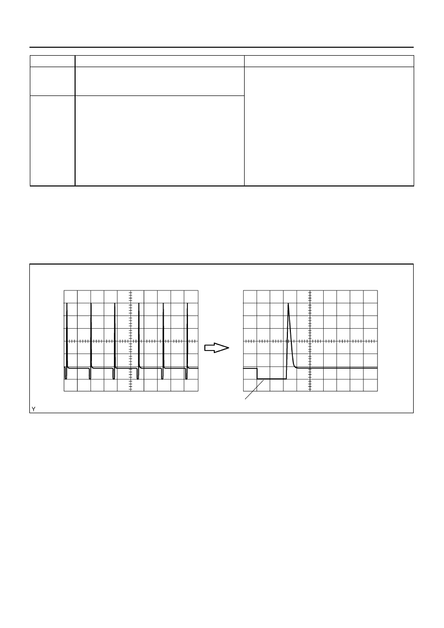
20 V
/Division
Injector Signal Waveform
20 V
/Division
GND
100 msec./Division (Idling)
(Magnification)
GND
1 msec./Division (Idling)
Injection duration
–
DIAGNOSTICS
ENGINE
DI–185
379
DTC No.
DTC Detecting Condition
Trouble Area
P0300
Misfiring of random cylinders is detected
Open or short in engine wire
Connector connection
Vacuum hose connection
P0301
P0302
P0303
P0304
P0305
P0306
P0307
P0308
Misfiring of each cylinder is detected
Vacuum hose connection
Ignition system
Injector
Fuel pressure
Mass air flow meter
Engine coolant temperature sensor
Compression pressure
Valve clearance
Valve timing
PCV piping
ECM
HINT:
When several codes for a misfiring cylinder are recorded repeatedly but no random misfire code is recorded,
it indicates that the misfires have been detected and recorded at different times.
Reference: Inspection using the oscilloscope.
With the engine idling, check the waveform between terminals #1 to #8 and E01 of the ECM connectors.
HINT:
The correct waveform is as shown in the illustration.
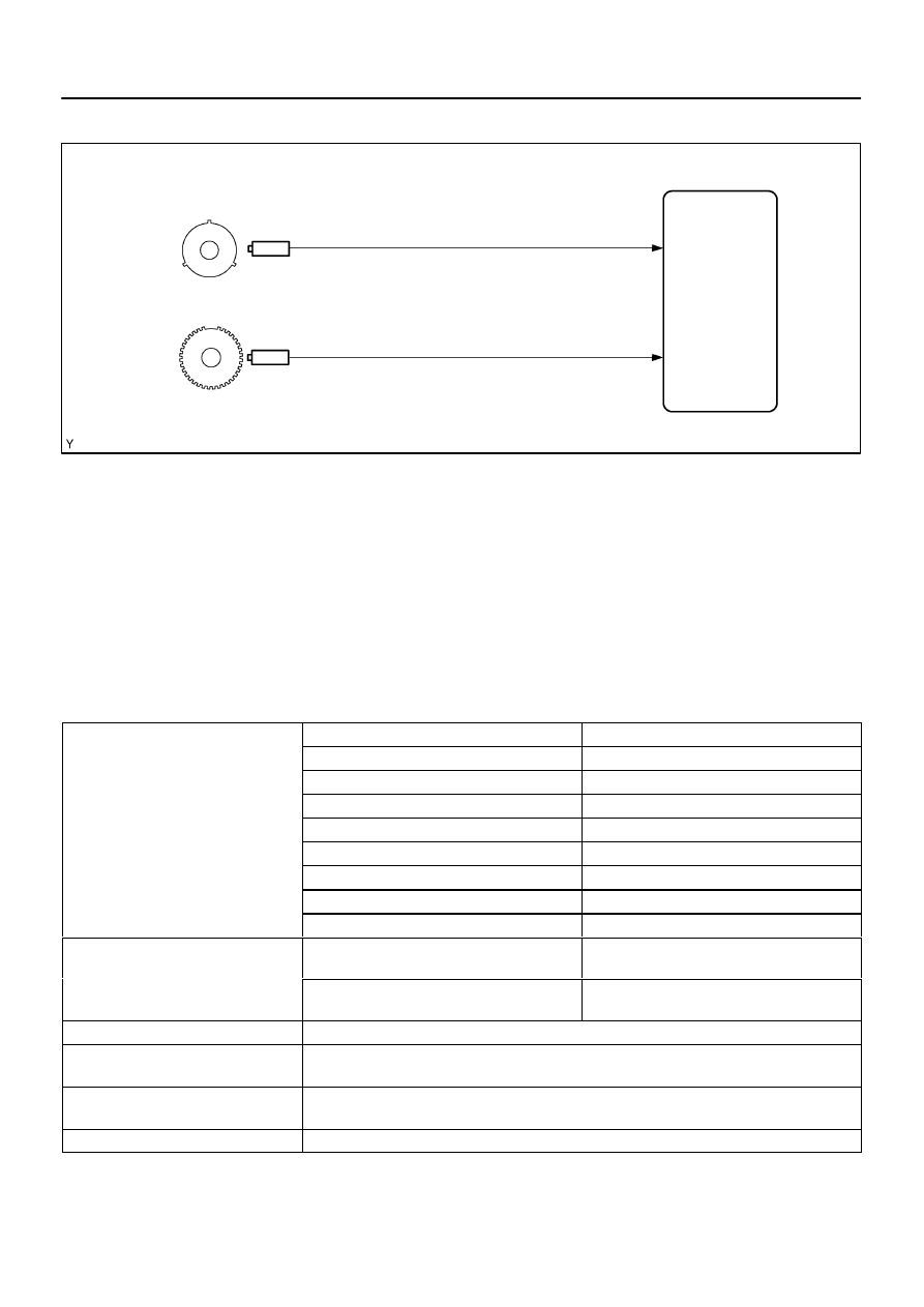
Crankshaft position sensor
(36–2 teeth or 12 teeth)
Camshaft position sensor
ECM
A20490
DI–186
–
DIAGNOSTICS
ENGINE
380
MONITOR DESCRIPTION
The ECM illuminates the MIL (2 trip detection logic) if:
The ECM will illuminate the MIL when the percentage of misfire exceeds the specified limit per 1,000 engine
revolutions. One occurrence of excessive misfire during engine start will set the MIL. Four occurrences are
required to set the MIL 1,000 revolutions after engine start.
The ECM blinks the MIL (the MIL blinks immediately) if:
Within 200 engine revolutions at a high rpm, the threshold for ”percentage of misfire causing catalyst
damage” is reached 1 time.
Within 200 engine revolutions at a normal rpm, the threshold for ”percentage of misfire causing catalyst
damage” is reached 3 time.
MONITOR STRATEGY
P0300
Random/Multiple cylinder misfire detected
P0301
Cylinder 1 misfire detected
P0302
Cylinder 2 misfire detected
P0303
Cylinder 3 misfire detected
Related DTCs
P0304
Cylinder 4 misfire detected
Related DTCs
P0305
Cylinder 5 misfire detected
P0306
Cylinder 6 misfire detected
P0307
Cylinder 7 misfire detected
P0308
Cylinder 8 misfire detected
R
i d
/
t
Main sensors/components
Camshaft position sensor, Crankshaft position
sensor
Required sensors/components
Related sensors/components
Engine coolant temperature sensor, Intake air
temperature sensor, Throttle position sensor
Frequency of operation
Continuous
Duration
Every 1,000 revolutions (soon after engine is started: 1 time, other: 4 times) (emission related misfire)
Every 200 revolutions (1 or 3 times) (catalyst deteriorating misfire)
MIL operation
2 driving cycles MIL ON
Immediate MIL blinking (Catalyst deteriorating misfire)
Sequence of operation
None
Нет комментариевНе стесняйтесь поделиться с нами вашим ценным мнением.
Текст