Toyota Sequoia (2005). Manual — part 93
A19288
A/F Relay
A23659
Wire Harness Side:
HT
A38
Sensor 1
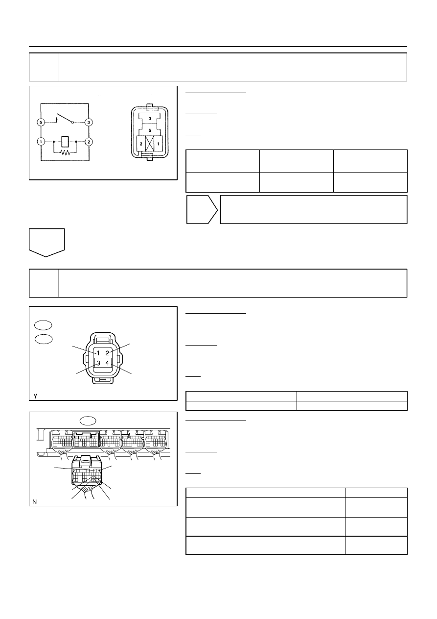
A/F Sensor Connector
AF+
Front View
AF–
+B
A39
B17415
E7 ECM Connector
HA1A
A1A+
A1A–
A2A+
A2A–
HA2A
–
DIAGNOSTICS
ENGINE
DI–175
369
12
Check A/F relay.
PREPARATION:
Remove the A/F relay from the engine room J/B.
CHECK:
Inspect the A/F relay.
OK:
Standard:
Terminal No.
Condition
Specified Condition
3 – 5
Always
10 K
Ω
or higher
3 – 5
Apply B+ between
terminals 1 and 2
Below 1
Ω
NG
Replace A/F relay.
OK
13
Check for open and short in harness and connector between ECM and A/F sen-
sor.
PREPARATION:
(a)
Disconnect the A38 or A39 A/F sensor connector.
(b)
Turn the ignition switch to ON.
CHECK:
(a)
Measure the voltage between the +B terminal of the A/F
sensor connector and body ground.
OK:
Standard:
Tester Connections
Specified Conditions
+B (2) – Body ground
9 to 14 V
PREPARATION:
(a)
Turn the ignition switch to OFF.
(b)
Disconnect the E7 ECM connector.
CHECK:
(a)
Check the resistance.
OK:
Standard (Check for open):
Tester Connections
Specified Conditions
HT (A38–1) – HA1A (E7–2)
HT (A39–1) – HA2A (E7–1)
Below 1
Ω
AF+ (A38–3) – A1A+ (E7–22)
AF+ (A39–3) – A2A+ (E7–23)
Below 1
Ω
AF– (A38–4) – A1A– (E7–30)
AF– (A39–4) – A2A– (E7–31)
Below 1
Ω
A23512
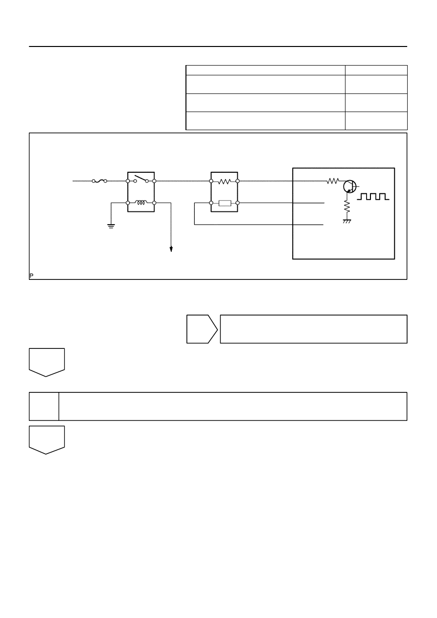
Reference (Bank 1 Sensor 1 System Drawing):
A/F Sensor
A/F Relay
Heater
Sensor
A1A+
HA1A
Duty
Control
ECM
From
Battery
A/F Heater
Fuse
A1A–
To EFI Relay
DI–176
–
DIAGNOSTICS
ENGINE
370
Standard (Check for short):
Tester Connections
Specified Conditions
HT (A38–1) or HA1A (E7–2) – Body ground
HT (A39–1) or HA2A (E7–1) – Body ground
10 k
Ω
or higher
AF+ (A38–3) or A1A+ (E7–22) – Body ground
AF+ (A39–3) or A2A+ (E7–23) – Body ground
10 k
Ω
or higher
AF– (A38–4) or A1A– (E7–30) – Body ground
AF– (A39–4) or A2A– (E7–31) – Body ground
10 k
Ω
or higher
NG
Replace or replace harness or connector.
OK
14
Replace air fuel ratio sensor.
NEXT
B17397
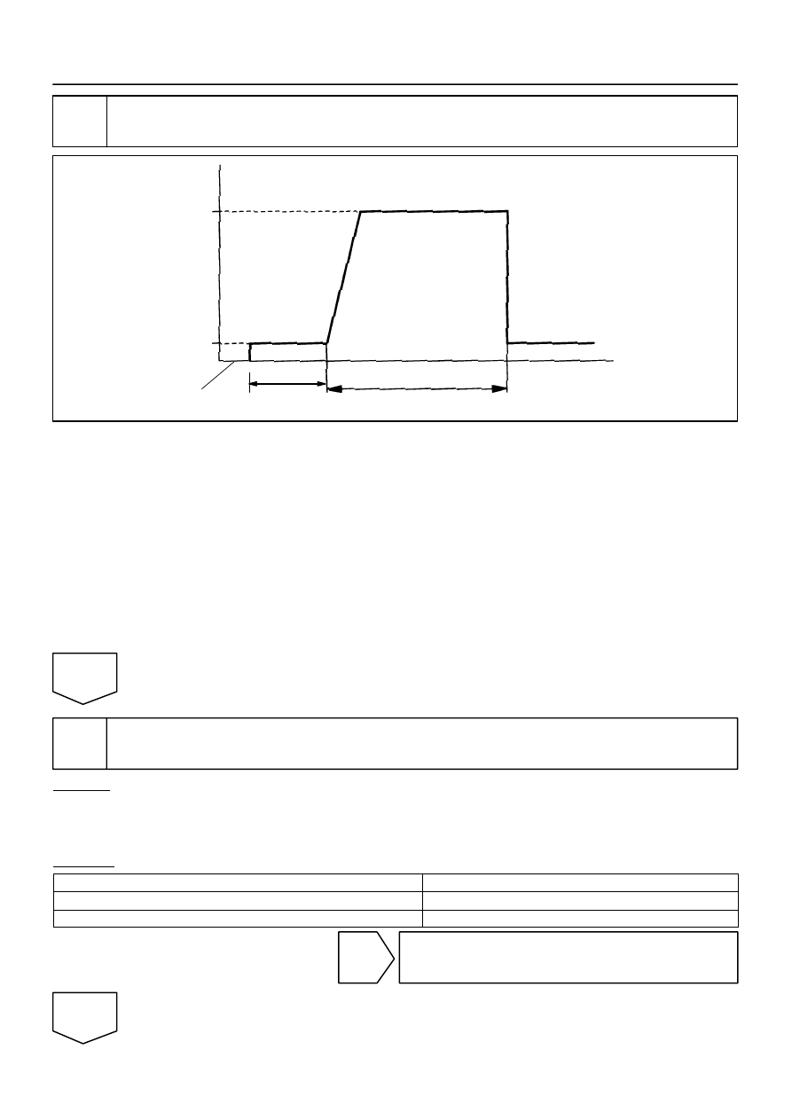
Vehicle Speed
Between
38 mph and 75 mph
(60 km/h and 120 km/h)
Idling
Ignition Switch OFF
3 to 5 minutes
Time
2 minutes
(a), (b), (c)
(e)
(d)
–
DIAGNOSTICS
ENGINE
DI–177
371
15
Perform confirmation driving pattern.
(a)
Connect the hand–held tester to the DLC3.
(b)
Turn the ignition switch to ON and turn the tester ON.
(c)
Clear DTCs (see page
(d)
Switch the ECM from normal mode to check mode using the tester (see page
).
(e)
Start the engine and warm it up with all the accessories switched OFF.
(f)
Drive the vehicle at between 38 mph and 75 mph (60 km/h and 120 km/h) and at an engine speed of
between 1,400 rpm and 3,200 rpm for 3 to 5 minutes.
HINT:
If the system is still malfunctioning, the MIL will be illuminated during step (e).
NOTICE:
If the conditions in this test are not strictly followed, no malfunction will be detected.
NEXT
16
Check whether DTC output recurs (DTC P0171, P0172, P0174 or P0175)
CHECK:
(a)
On the hand–held tester, select the following menu items: DIAGNOSIS / ENHANCED OBD II / DTC
INFO / PENDING CODES.
(b)
Read DTCs.
RESULT:
Display (DTC Output)
Proceed To
P0171, P0172, P0174 or P0175
A
No output
B
B
Go to step 5.
A
DI–178
–
DIAGNOSTICS
ENGINE
372
END
Нет комментариевНе стесняйтесь поделиться с нами вашим ценным мнением.
Текст