Toyota Sequoia (2005). Manual — part 242
F19445
Engine Room R/B No. 2
F10
Fusible Link Block
Suspension Control
ECU
AIR SUS No. 2
2
1
2
2
W
AIR SUS
9
ALT
5
B
Battery
IF
J12
J/C
A
W–B
22
S25 GND
24
S25
25
S25 BAT
B
J/C
B
J37
B
J37
C
J38
V
IA5
5
V
V
V
–
DIAGNOSTICS
AIR SUSPENSION SYSTEM
DI–763
957
DTC
C1774/74 Power Source Circuit
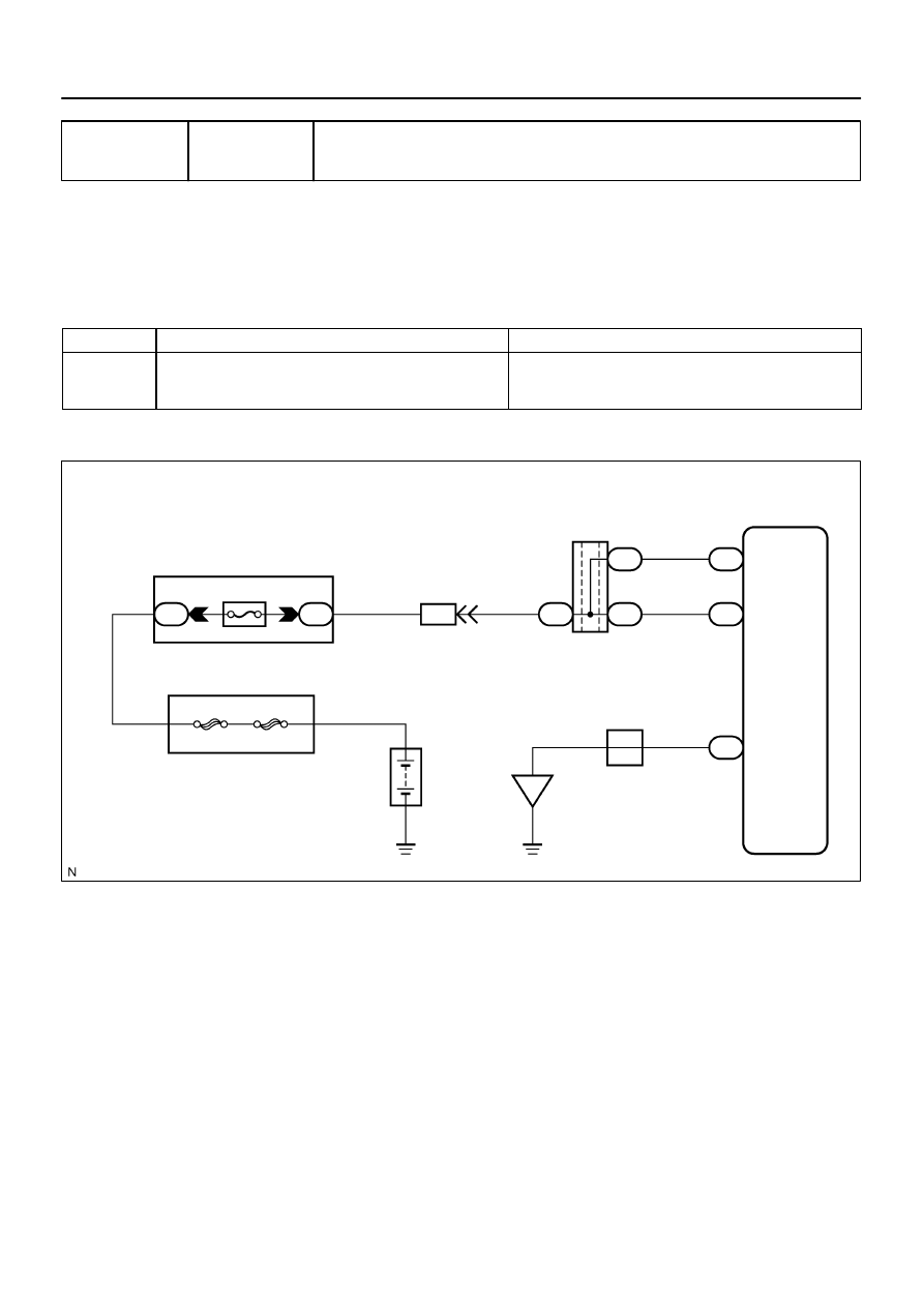
CIRCUIT DESCRIPTION
This circuit provides power to operate the suspension control ECU.
The suspension control ECU, controlling the air suspension system, is activated when the ignition
switch is turned ON. The main relay inside the ECU is activated after 2 seconds and the system is oper-
ated by +B power source.
DTC No.
DTC Detecting Condition
Trouble Area
C1774/74
The terminal B or BAT voltage is below 10 V or above 16 V for
0.5 seconds.
Battery
Power source circuit
Suspension control ECU
WIRING DIAGRAM
DIDE3–01
DI–764
–
DIAGNOSTICS
AIR SUSPENSION SYSTEM
958
INSPECTION PROCEDURE
1
Inspect battery voltage.
CHECK:
Check the battery voltage.
OK:
Voltage: 11 to 14 V
NG
Replace battery.
OK
HINT:
Start the inspection from step 2 when using the hand–held tester, and start from step 3 when not using the
hand–held tester.
2
Read value of the hand–held tester.
PREPARATION:
(a)
Connect the hand–held tester to the DLC3.
(b)
Turn the ignition switch ON, and push the hand–held tester main switch ON.
(c)
Select the item ”POWER VOLTAGE” in the DATA LIST, and read its value displayed on the hand–held
tester.
AIR SUSPENSION:
Item
Measurement Item / Range (Dis-
play)
Normal Condition
Diagnostic Note
POWER VOLTAGE
+B power source voltage / min.: 0
V, max.: 25.5 V
Actual battery power supply volt-
age: 10 to 14 V
–
CHECK:
Check the battery positive voltage.
OK:
Actual battery power supply voltage: 10 to 14 V
RESULT:
NG
A
OK (When troubleshooting according to the PROBLEM SYMPTOMS TABLE)
B
OK (When troubleshooting according to the DTC chart)
C
B
Proceed to next circuit inspection shown in
problem symptoms table (See page
C
Check for intermittent problems.
F16805
S25
BAT
B
Wire Harness View:
–
DIAGNOSTICS
AIR SUSPENSION SYSTEM
DI–765
959
A
3
Inspect fuse (AIR SUS No. 2).
PREPARATION:
Remove the AIR SUS No. 2 fuse from the engine room R/B.
CHECK:
Check continuity of the AIR SUS No. 2 fuse.
OK:
Continuity
NG
Inspect for short circuit in all harness and com-
ponents connected to AIR SUS No. 2 fuse.
OK
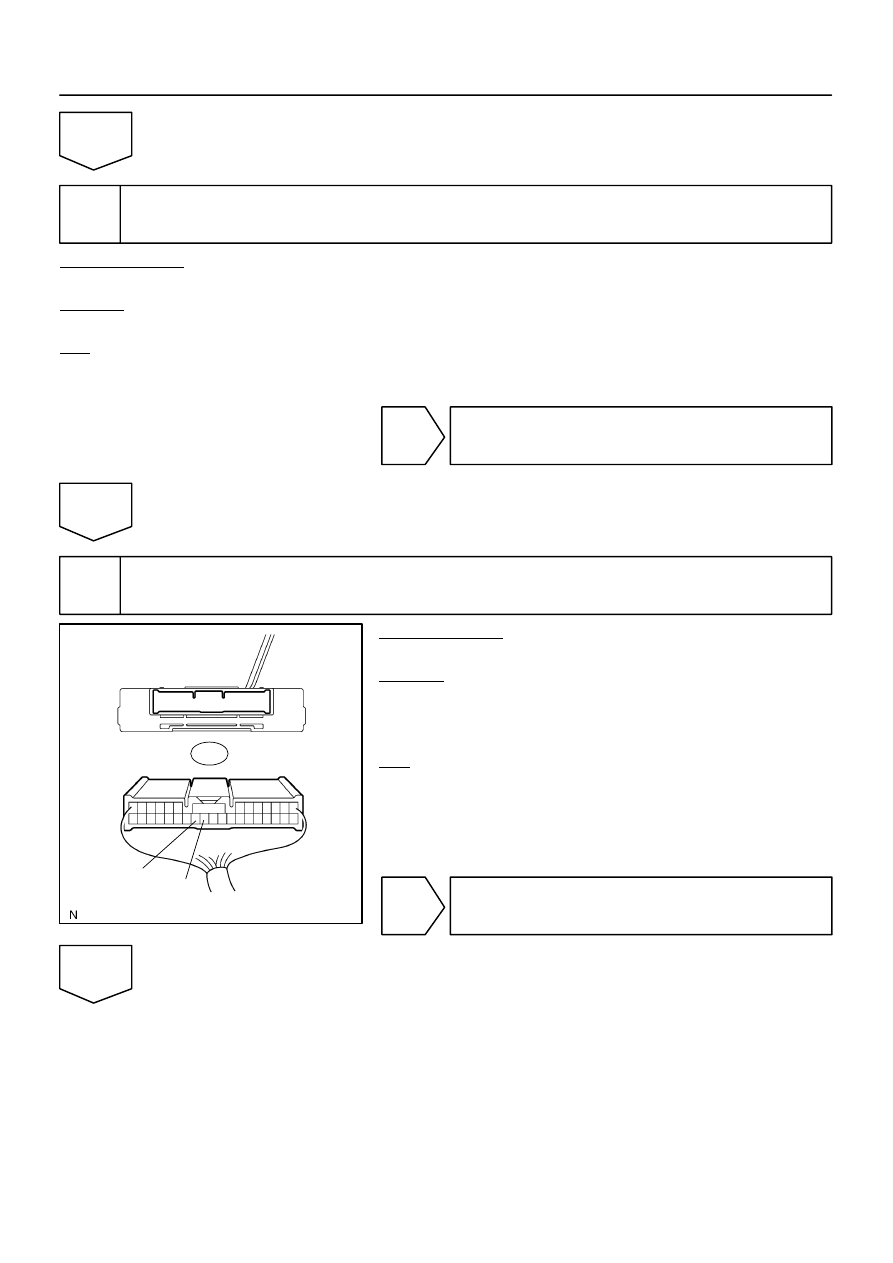
4
Inspect suspension control ECU.
PREPARATION:
Disconnect the ECU connector.
CHECK:
Measure the voltage between terminal S25–24 (B) of the sus-
pension control ECU connector and body ground and between
terminal S25–25 (BAT) and body ground.
OK:
Voltage: 10 to 14 V
NG
Repair or replace harness or connector.
OK
F16805
Wire Harness View:
GND
S25
DI–766
–
DIAGNOSTICS
AIR SUSPENSION SYSTEM
960
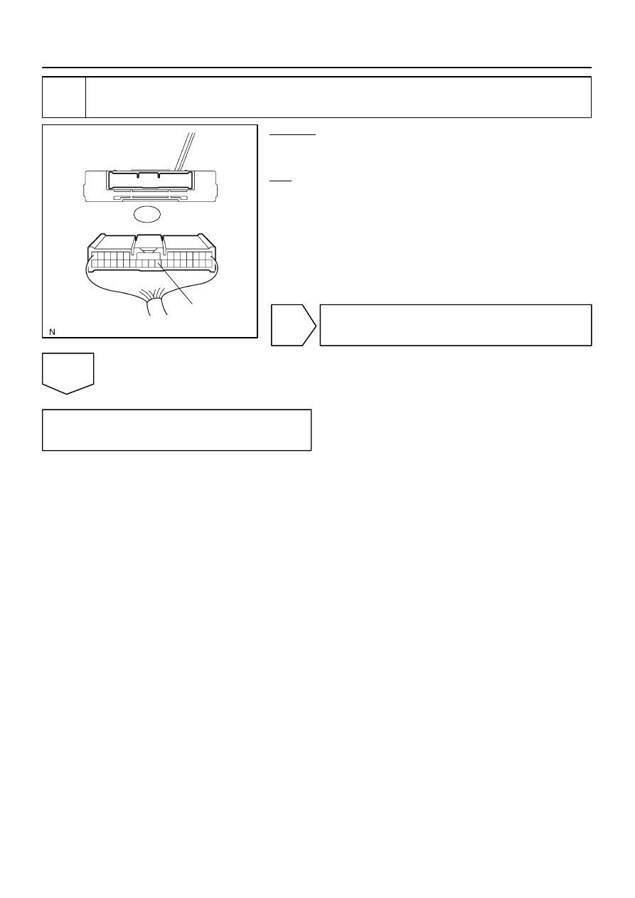
5
Check harness and connector (Suspension control ECU – Body ground).
CHECK:
Check continuity between terminal S25–22 (GND) and body
ground.
OK:
Continuity
NG
Repair or replace harness or connector.
OK
Replace suspension control ECU
(See page
).
Нет комментариевНе стесняйтесь поделиться с нами вашим ценным мнением.
Текст