Toyota Sequoia (2005). Manual — part 241
F19437
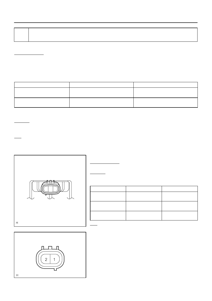
Height Control Valve
Connector Front View:
3 2 1
F19457
Height Control Compressor
Connector Front View:
–
DIAGNOSTICS
AIR SUSPENSION SYSTEM
DI–759
953
3
Inspect height control valve (Gate solenoid valve, Leveling solenoid valve) or
height control compressor (Exhaust solenoid valve).
When using hand–held tester:
PREPARATION:
(a)
Connect the hand–held tester to the DLC3.
(b)
Turn the ignition switch ON, and push the hand–held tester main switch ON.
(c)
Select the item ”LEVEL SOL REAR”, ”GATE SOL REAR” in the ACTIVE TEST, and operate it with the
hand–held tester.
AIR SUSPENSION:
Item
Vehicle Condition / Test Details
Diagnostic Note
LEVEL SOL REAR
Turn leveling solenoid valve / ON or OFF
Operation sound of solenoid (clicking sound) can
be heard
GATE SOL REAR
Turn gate solenoid valve / ON or OFF
Operation sound of solenoid (clicking sound) can
be heard
HINT:
The exhaust solenoid valve cannot be tested in ACTIVE TEST.
CHECK:
(a)
Check whether the solenoid makes a sound.
(b)
Check whether the height control solenoid valve has continuity (will vibrate).
OK:
The solenoid makes a sound, and the height control solenoid valve has continuity. (It will vi-
brate.)
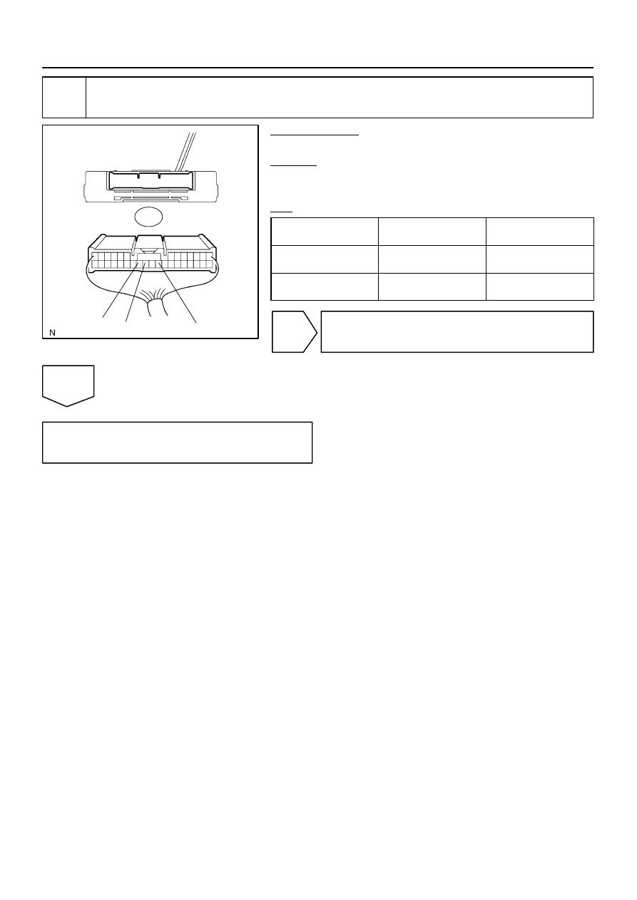
When not using hand–held tester:
PREPARATION:
Disconnect the valve connector.
CHECK:
Check the operating sound of the valves when battery positive
voltage is applied to the terminals as shown below.
Solenoid valve
Battery positive
Battery negative
Height control valve
(Gate solenoid valve)
1
2
Height control valve
(Leveling solenoid valve)
3
2
Height control compressor
(Exhaust solenoid valve)
1
2
OK:
It make an operating sound (click).
HINT:
When a malfunction is found in the gate solenoid valve,
replace the leveling valve and the height control valve.
When a malfunction is found in the exhaust solenoid
valve, replace the height control compressor assy.
DI–760
–
DIAGNOSTICS
AIR SUSPENSION SYSTEM
954
NG
Replace height control valve assy
(See page
NG
Replace height control compressor assy
(See page
OK
4
Inspect height control sensor sub–assy.
CHECK:
Inspect and adjust the height control sensor sub–assy (See page
NEXT
5
Reconfirm DTC.
CHECK:
Clear the DTC and repeat the procedure to re–check it (See page
).
HINT:
If the DTC C1751/51 is still output, proceed to the next step.
NEXT
Check and repair or replace malfunctioning
parts.
(a)
Air tube is clogged (See page
(b)
Compressor is faulty (See page
).
(c)
Relief valve is faulty (See page
(d)
Height control sensor sub–assy is faulty (See page
).
(e)
Foreign material entered the height control solenoid valve (gate solenoid valve) and the exhaust sole-
noid valve.
(f)
Air leakage due to damage to the height control cylinder assy (pneumatic cylinder).
(g)
–
DIAGNOSTICS
AIR SUSPENSION SYSTEM
DI–761
955
DTC
C1761/61 ECU Malfunction
CIRCUIT DESCRIPTION
DTC No.
DTC Detecting Condition
Trouble Area
C1761/61
Suspension control ECU malfunction
Power source circuit
Suspension control ECU
Communication circuit
INSPECTION PROCEDURE
HINT:
If DTC C1774/74 (power source circuit) is displayed, perform the inspection necessary for DTC
C1774/74 first (See page
If DTC U0122/67, U0100/65, U0132/71 and C1761/61 (ECU malfunction) are output at the same time,
perform the inspection necessary for the CAN communication system first.
The suspension control ECU, controlling the air suspension system, is activated when the ignition
switch is turned ON.
After 2 seconds, the ”MAIN RELAY” built in the ECU is activated and the system is driven by +B power
source.
Vehicle height may increase after turning the ignition switch off and unloading the vehicle/letting
people get out of the vehicle. In order to adjust the vehicle height, vehicle height control will continue
for a while from then.
DIDDY–01
F16805
S25
Wire Harness View:
BAT
B
GND
DI–762
–
DIAGNOSTICS
AIR SUSPENSION SYSTEM
956
1
Inspect suspension control ECU (ECU power source).
PREPARATION:
Disconnect the ECU connector.
CHECK:
Measure the voltage according to the value(s) in the table be-
low.
OK:
Tester connection
(Symbol)
Condition
specified condition
S25–24 (B) –
S25–22 (GND)
Always
10 to 14 V
S25–25 (BAT) –
S25–22 (GND)
Always
10 to 14 V
NG
Check power source circuit
(See page
).
OK
Replace suspension control ECU
(See page
).
Нет комментариевНе стесняйтесь поделиться с нами вашим ценным мнением.
Текст