Toyota Sequoia (2005). Manual — part 230
–
DIAGNOSTICS
AIR SUSPENSION SYSTEM
DI–715
909
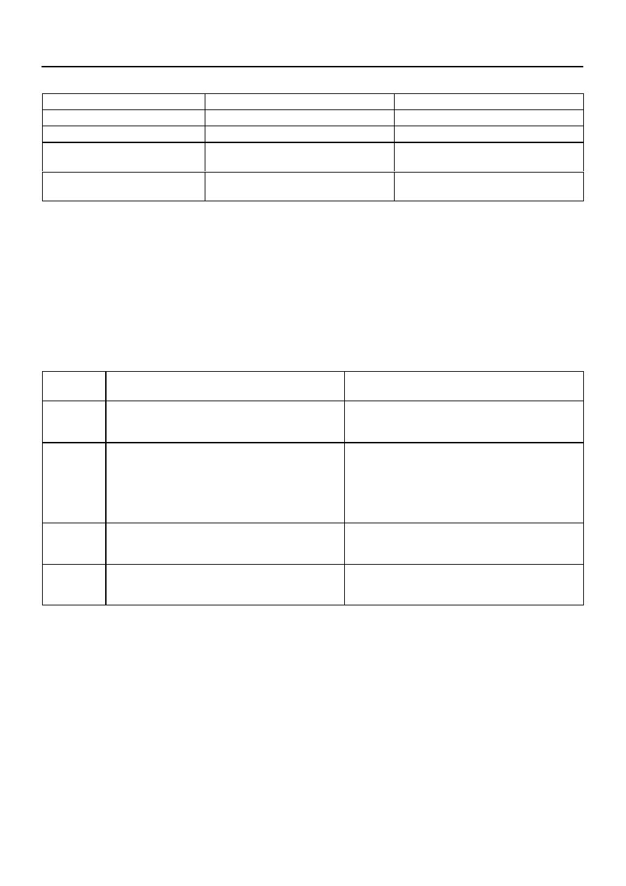
Test mode (input signal check) table:
Check Item
Operation (A)
Operation (B)
Stop light switch signal
OFF (Brake pedal not depressed)
ON (Brake pedal depressed)
Door courtesy light switch signal
ON (Each door opened)
OFF (All doors closed)
Height control switch signal
–
Press the height control switch ”UP” first and
then press ”DOWN”
Height control mode select switch signal
OFF (Height control mode select switch not
pushed in)
ON to OFF (Height control mode select switch
pushed in and released)
HINT:
In step (6), all signals can be checked together.
(7)
Read the test mode DTCs by following the prompts
on the tester screen.
HINT:
Refer to the hand–held tester operator’s manual for further de-
tails.
(8)
Check the malfunction using the code table below.
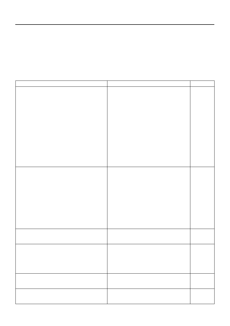
DTC of air suspension system test mode (input signal check) function:
If a trouble code is displayed during the test mode DTC check, check the circuit listed for that code. For details
of each code, refer to ”See page” under the respective DTC No. in the chart.
DTC No.
(See Page)
Detection Item
Trouble Area
C1782/82
(
)
Stop light switch circuit malfunction
Stop light switch assy
Stop light switch circuit
Suspension control ECU
C1783/83
(
)
Door courtesy switch circuit malfunction
Door courtesy light switch assy
W/ Motor back door assy
Door courtesy light switch circuit
Body ECU
Back door ECU
Suspension control ECU
C1786/86
(
)
Height control switch circuit malfunction
Height control switch
Height control switch circuit
Suspension control ECU
C1788/88
(
)
Height control mode select switch circuit malfunction
Height control mode select switch
Height control mode select switch circuit
Suspension control ECU
(9)
After completing the test mode, disconnect the tes-
ter and turn the ignition switch off.
DIDCZ–01
DI–716
–
DIAGNOSTICS
AIR SUSPENSION SYSTEM
910
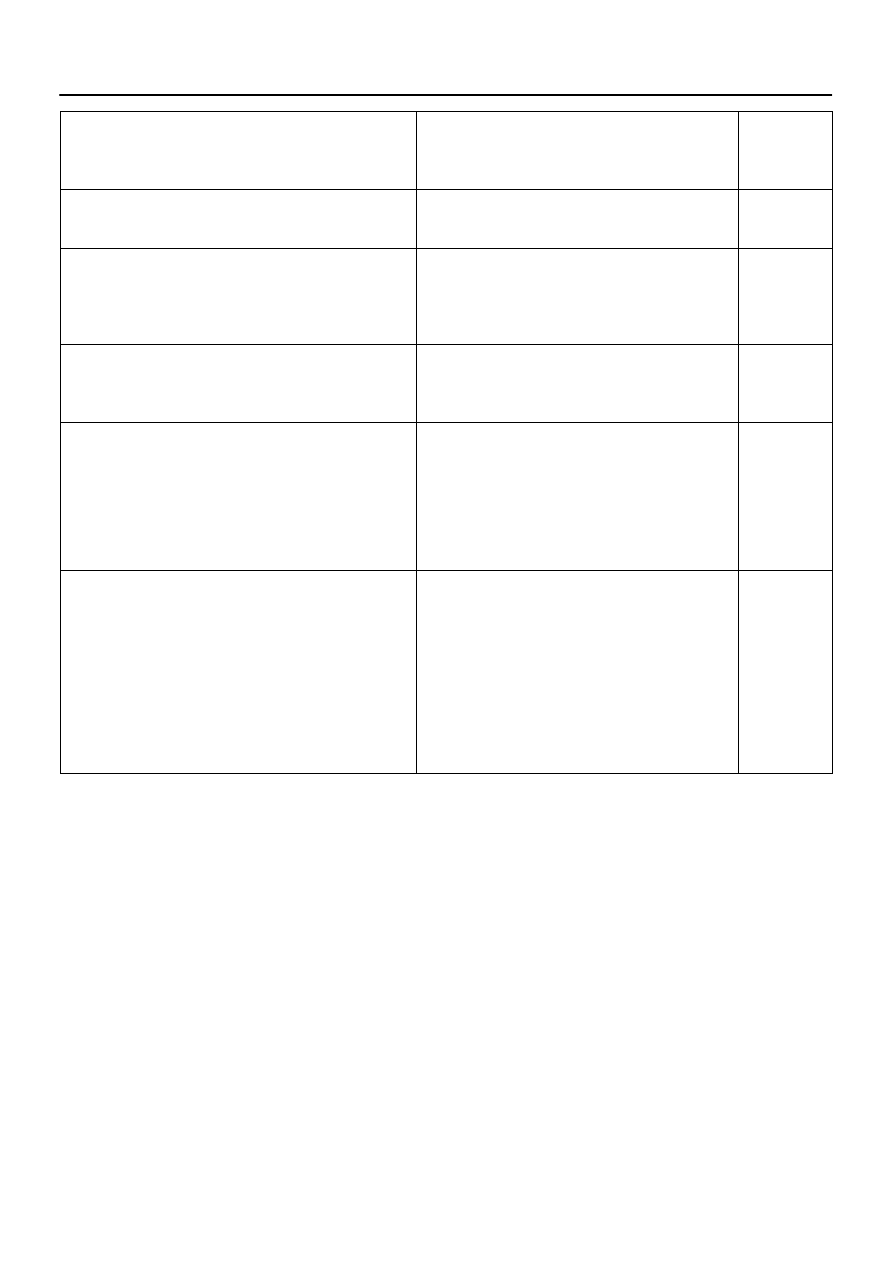
PROBLEM SYMPTOMS TABLE
HINT:
If a normal system code is displayed during the DTC check but the problem still occurs, check the cir-
cuits for each problem symptom in the order given in the table below and proceed to the relevant trou-
bleshooting page.
Inspect the fuse before inspecting the suspected areas as shown in the chart below.
Inspect each malfunction circuit in numerical order for the corresponding symptom.
If the malfunction still exists even after checking and confirming that all the circuits are normal, replace
the suspension control ECU.
Symptom
Suspected Area
See page
Vehicle height control function does not operate.
If the compressor remains on for an excessive period of
time or turns on and off repeatedly, the system control will
be halted for up to 70 minutes, after which the system will
return to normal operation.
1. Air tube is seized
2. Power source circuit
3. IG signal circuit
4. Crankshaft position sensor circuit
5. Height control mode select switch circuit
6. Height control switch circuit
7. Height control sensor circuit
8. Leveling solenoid valve circuit
9. Gate solenoid valve circuit
10.Exhaust solenoid valve circuit
11.AIR SUS relay circuit
12.Height control compressor circuit
13.Suspension control ECU
–
Illuminated position of height control indicator lamp does not
change by the height control switch operation.
1. Power source circuit
2. Crankshaft position sensor circuit
3. Height control mode select switch circuit
4. Height control switch circuit
5. Height control sensor circuit
6. Leveling solenoid valve circuit
7. Gate solenoid valve circuit
8. Exhaust solenoid valve circuit
9. AIR SUS relay circuit
10.Height control compressor circuit
11.Speed sensor circuit
12.CAN communication circuit
13.Suspension control ECU
Hunting of vehicle height occurs.
1. Air leakage
(Height control cylinder assy rear)
2. Height control sensor circuit
3. Suspension control ECU
Vehicle height control operates, but vehicle height is uneven.
1. Air leakage
2. Clogging of the air tube
3. Height control sensor link sub–assy
4. Height control sensor circuit
5. Gate solenoid valve circuit
6. Suspension control ECU
–
Vehicle height control operates, but vehicle height is high or
low (Vehicle height in NORMAL mode differs from the standard
value).
1. Height control sensor link sub–assy
2. Height control sensor circuit
3. Suspension control ECU
When vehicle height control is adjusted, it stops at extremely high
or low position.
1. Height control sensor circuit
2. Height control sensor link sub–assy
3. Suspension control ECU
–
DIAGNOSTICS
AIR SUSPENSION SYSTEM
DI–717
911
Height control manual indicator lamp condition is abnormal.
1. Power source circuit
2. Height control mode select switch circuit
3. Height control manual indicator lamp circuit
4. Suspension control ECU
Height control indicator lamp condition is abnormal.
1. Power source circuit
2. Height control indicator lamp circuit
3. Suspension control ECU
DTC check cannot be completed.
1. Power source circuit
2. CAN communication system
3. Height control manual indicator lamp circuit
4. Suspension control ECU
5. ECM
Input signal check (test mode) cannot be completed.
1. Power source circuit
2. CAN communication system
3. Suspension control ECU
4. Translate ECU
Vehicle height is extremely low when vehicle is parked.
Although, especially in a cold district, the vehicle height
may become lower due to a drop in air temperature in the
height control cylinder assy, but this is not abnormal.
1. Air leakage
2. Height control cylinder assy
3. Height control sensor link sub–assy
4. Leveling solenoid valve circuit
5. Exhaust valve circuit
–
Compressor motor continues to operate.
Due to the air tube freezing, vehicle height may not rise.
1. Air leakage
2. Air tube clogged
3. Height control cylinder assy
4. Height control sensor link sub–assy
5. Height control sensor circuit
6. Leveling solenoid valve circuit
7. Exhaust valve circuit
8. AIR SUS relay circuit
9. Height control compressor circuit
10.Suspension control ECU
–
–
DIDD3–01
F16803
S25
DI–718
–
DIAGNOSTICS
AIR SUSPENSION SYSTEM
912
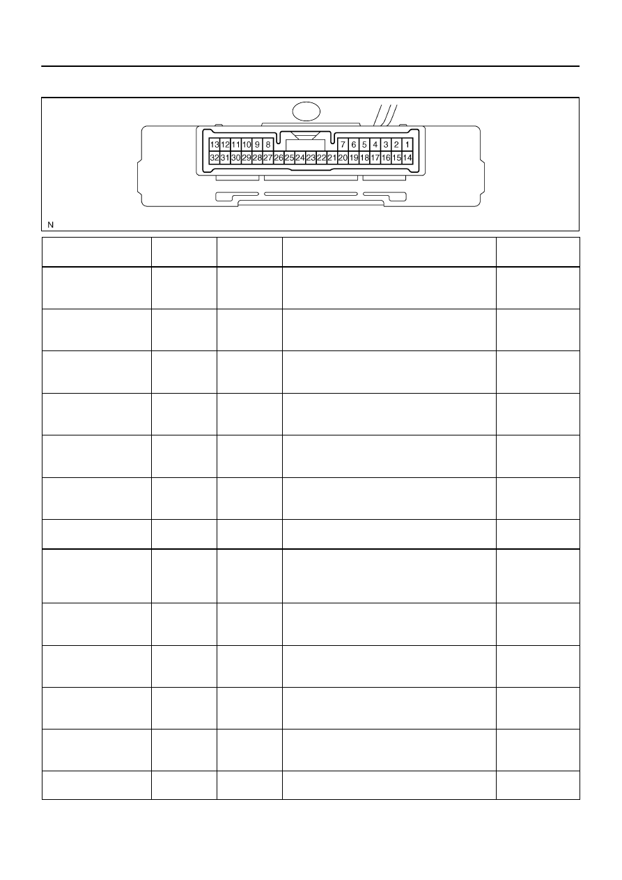
TERMINALS OF ECU
Symbols (Terminal No.)
Wiring Color
Terminal
Description
Condition
Specified Condition
SLEX (S25–1) –
L R
W B
Exhaust Sole-
id V l
Si
IG switch ON
→
E
i
idli
b tt
f h i ht
t l
it h i
h d
Below 1.0 V
→
SLEX (S25 1)
GND (S25–22)
L–R – W–B
noid Valve Sig-
nal
Engine idling, button of height control switch is pushed
from ”UP” to ”DOWN”
Below 1.0 V
→
9 V or more
SLRR (S25–3) –
LG R
W B
Leveling Sole-
id V l
Si
IG switch ON
→
E
i
idli
b tt
f h i ht
t l
it h i
h d
Below 1.0 V
→
SLRR (S25 3)
GND (S25–22)
LG–R – W–B
noid Valve Sig-
nal
Engine idling, button of height control switch is pushed
from ”DOWN” to ”UP”
Below 1.0 V
→
9 V or more
SLRL (S25–4) –
W L
W B
Gate Solenoid
IG switch ON
→
E
i
idli
b tt
f h i ht
t l
it h i
h d
Below 1.0 V
→
SLRL (S25 4)
GND (S25–22)
W–L – W–B
Gate Solenoid
Valve Signal
Engine idling, button of height control switch is pushed
from ”DOWN” to ”UP”
Below 1.0 V
→
9 V or more
RC (S25–5) –
G Y
W B
AIR SUS Relay
IG switch ON
→
E
i
idli
b tt
f h i ht
t l
it h i
h d
Below 1.0 V
→
RC (S25 5)
GND (S25–22)
G–Y – W–B
AIR SUS Relay
Signal
Engine idling, button of height control switch is pushed
from ”N” to ”UP”
Below 1.0 V
→
9 V or more
HI (S25–8) –
GR R
W B
Height Control
I di
t
”HI”
Engine idling, vehicle height is ”NORMAL”
→
P
i
th ”UP” b tt
f th
t l
it h t
10 V or more
→
HI (S25 8)
GND (S25–22)
GR–R – W–B
Indicator ”HI”
Signal
Pressing the ”UP” button of the control switch turns on
the ”HI” indicator lamp (*1)
10 V or more
→
Below 5 V
NR (S25–9) –
B L
W B
Height Control
I di
t
”N”
Engine idling, vehicle height is ”NORMAL”
→
P
i
th ”UP” b tt
f th
t l
it h t
Below 5 V
→
NR (S25 9)
GND (S25–22)
B–L – W–B
Indicator ”N”
Signal
Pressing the ”UP” button of the control switch turns on
the ”HI” indicator lamp (*1)
Below 5 V
→
10 V or more
IG (S25–10) –
GND (S25–22)
B–R – W–B
Ignition Switch
IG switch ON
10 to 14 V
VN (S25–11) –
LG
W B
Height Control
M
l I di
IG switch ON, height control manual indicator lamp ON
→
Pressing and releasing the height control mode select
Below 5 V
→
VN (S25 11)
GND (S25–22)
LG – W–B
Manual Indica-
tor Lamp Signal
→
Pressing and releasing the height control mode select
switch turns off the height control manual indicator lamp
(*1)
Below 5 V
→
10 V or more
TD (S25–12) –
BR B
W B
Height Control
M d S l
t
IG switch ON, height control mode select switch pushed
i
Below 1.5 V
→
TD (S25 12)
GND (S25–22)
BR–B – W–B
Mode Select
Switch
in
→
Height control select switch released
Below 1.5 V
→
10 to 14 V
UPSW (S25–13) –
L B
W B
Height Control
S it h ”UP”
IG switch ON, ”UP” button of height control switch
h d i
Below 1.5 V
→
UPSW (S25 13)
GND (S25–22)
L–B – W–B
Switch ”UP”
Signal
pushed in
→
”UP” button of height control switch released
Below 1.5 V
→
10 to 14 V
SBL (S25–15) –
SGL (S25–19)
G–O – L–R
Height Control
Sensor Power
Source
IG switch ON
4.5 to 5.5 V
SHRL (S25–17) –
GR L
L R
Height Control
S
I
t
IG switch ON
→
E
i
idli
hi l h i ht i
h
d f
”HIGH” t
0.5 to 4.5 V
→
SHRL (S25 17)
SGL (S25–19)
GR–L – L–R
Sensor Input
Signal
Engine idling, vehicle height is changed from ”HIGH” to
”NORMAL” by pressing the height control switch
0.5 to 4.5 V
→
Approx. 2.5 V
SGL (S25–19) –
GND (S25–22)
L–R – W–B
Height Control
Sensor Ground
Always
Below 1.0 V
Нет комментариевНе стесняйтесь поделиться с нами вашим ценным мнением.
Текст