Toyota Sequoia (2005). Manual — part 231

F16807
GND
F19430
GND
–
DIAGNOSTICS
AIR SUSPENSION SYSTEM
DI–719
913
RM+ (S25–20) –
GND (S25–22)
R–L – W–B
Height Control
Compressor
Motor Lock (+)
Engine idling, vehicle height changes from ”NORMAL” to
”HIGH” by pressing the height control switch (While
height control compressor assy is working).
Below 1.0 V
RM– (S25–21) –
Body ground
BR–Y – W–B
Height Control
Compressor
Motor Lock (–)
Always
Below 1.0 V
GND (S25–22) –
Body ground
W–B –
Body ground
Ground
Always
Below 1.0 V
B (S25–24) –
GND (S25–22)
V – W–B
Battery
IG switch ON
10 to 14 V
LO (S25–26) –
P
W B
Height Control
I di
t
”LO”
Engine idling, vehicle height is ”NORMAL”
→
P
i
th ”DOWN” b tt
f th h i ht
t l
it h
10 V or more
→
LO (S25 26)
GND (S25–22)
P – W–B
Indicator ”LO”
Signal
Pressing the ”DOWN” button of the height control switch
turns on the ”LO” indicator lamp (*1)
10 V or more
→
Below 5 V
STP (S25–27) –
G Y
W B
Stop Light
B k
d l d
d
R l
d
10 to 14 V
→
STP (S25 27)
GND (S25–22)
G–Y – W–B
Sto Light
Switch
Brake pedal depressed
→
Released
10 to 14 V
→
Below 1.5 V
SIL (S25–30) –
GND (S25–22)
G–R – W–B
Diagnosis Sig-
nal
Hand–held tester is connected to DLC3
Pulse generation
(See waveform 3)
DOOR (S25–31) –
R
W B
D
Si
l
IG switch ON, each door opened
→
Below 1.5 V
DOOR (S25 31)
GND (S25–22)
R – W–B
Door Signal
IG switch ON, each door o ened
→
All door closed
Below 1.5 V
10 to 14 V
DNSW (S25–32) –
GND (S25–22)
W – W–B
Height Control
Switch
”DOWN” Signal
IG switch ON, ”DOWN” button of height control switch
pushed in
→
”DOWN” button of height control switch released
Below 1.5 V
→
10 to 14 V
BAT (S25–25) –
GND (S25–22)
V – W–B
Battery
Always
10 to 14 V
CANL (S25–28) –
GND (S25–22)
W – W–B
CAN Commu-
nication Signal
IG switch ON
Pulse generation
(See waveform 1)
CANH (S25–29) –
GND (S25–22)
G – W–B
CAN Commu-
nication Signal
IG switch ON
Pulse generation
(See waveform 2)
*1: Perform inspection after checking that the height control indicator lamp switches are illuminated when
the height control switch button is pressed.
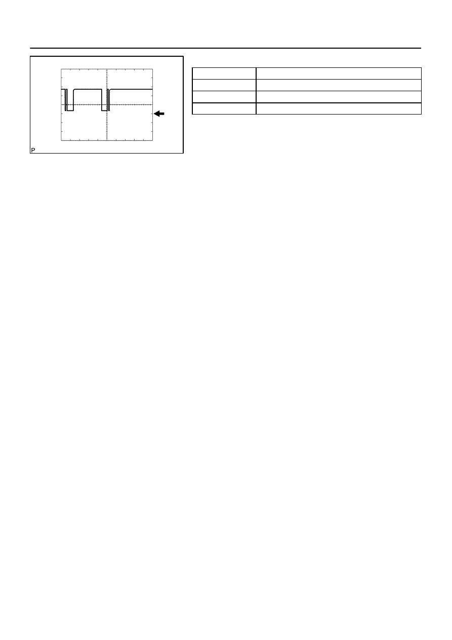
Waveform 1 (Reference):
Item
Contents
Terminal
CANL – GND
Tool setting
1V/DIV, 10
µ
s/DIV
Vehicle condition
Ignition SW ON, Engine stopped
Waveform 2 (Reference):
Item
Contents
Terminal
CANH – GND
Tool setting
1V/DIV, 10
µ
s/DIV
Vehicle condition
Ignition SW ON, Engine stopped
F19431
GND
DI–720
–
DIAGNOSTICS
AIR SUSPENSION SYSTEM
914
Waveform 3 (Reference):
Item
Contents
Terminal
SIL – GND
Tool setting
5V/DIV, 1ms/DIV
Vehicle condition
Communicating using hand–held tester
DIDD7–01
C00083
DLC3
–
DIAGNOSTICS
AIR SUSPENSION SYSTEM
DI–721
915
DIAGNOSIS SYSTEM
1.
DIAGNOSIS SYSTEM
(a)
Inspect the battery voltage.
Battery voltage: 11 to 14 V
If voltage is below 11 V, recharge the battery before proceeding.
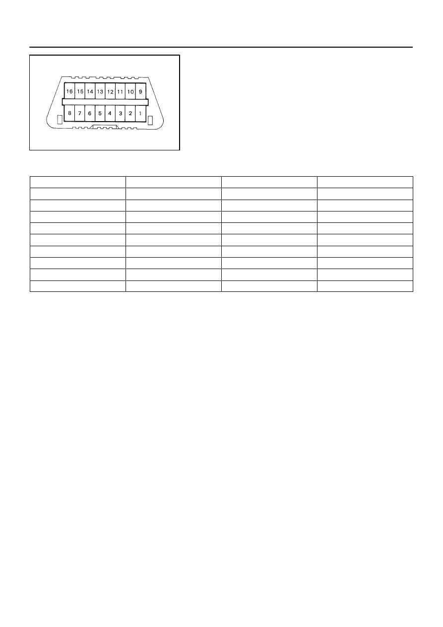
(b)
Check DLC3.
The suspension control ECU uses the CAN system and
ISO 9141–2 for communication. The terminal arrange-
ment of the DLC3 complies with SAE J1962 and matches
the ISO 9141–2 format.
Verify the conditions listed in the table below:
Symbols (Terminal No.)
Terminal Description
Condition
Specified Condition
SIL(7) – SG(5)
Bus ”+” line
During communication
Pulse generation
CG(4) – Body ground
Chassis ground
Always
Below 1
Ω
SG(5) – Body ground
Signal ground
Always
Below 1
Ω
BAT(16) – Body ground
Battery positive
Always
11 to 14 V
CANH(6) – CANL (14)
HIGH–level CAN bus line
IG switch OFF
54 to 67
Ω
CANH(6) – Battery positive
HIGH–level CAN bus line
IG switch OFF
1 M
Ω
or higher
CANH(6) – CG(4)
HIGH–level CAN bus line
IG switch OFF
3 K
Ω
or higher
CANL(14) – Battery positive
LOW–level CAN bus line
IG switch OFF
1 M
Ω
or higher
CANL(14) – CG(4)
LOW–level CAN bus line
IG switch OFF
3 K
Ω
or higher
HINT:
If the hand–held tester display shows UNABLE TO CONNECT
TO VEHICLE when the cable of the hand–held tester is con-
nected to the DLC3, the ignition switch is turned ON and the tes-
ter is operated, there is a problem on the vehicle side or tester
side.
If communication is normal when the tester is connected
to another vehicle, inspect the DLC3 on the original ve-
hicle.
If communication is still not possible when the tool is con-
nected to another vehicle, the problem is probably in the
tester itself, so consult the service department listed in the
tester’s instruction manual.
(c)
DTCs (Normal mode)
(1)
DTCs are memorized in the suspension control
ECU and read by using the SST check wire or the
hand–held tester (see page
for the proce-
dure of DTCs check).
SST
09843–18040
(d)
Test mode (Input signal check)
(1)
By switching from normal mode into test mode, you
can inspect the height control switch, height control
mode select switch, door courtesy lamp switch, and
stop lamp switch (see page
).
F16799
DI–722
–
DIAGNOSTICS
AIR SUSPENSION SYSTEM
916
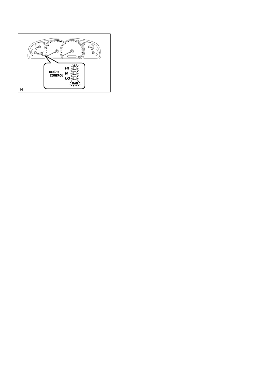
(e)
Check the indicator lamp.
(1)
Turn the ignition switch to the ON position.
(2)
Check that the height control manual indicator lamp
and the height control indicator lamp come on for 2
seconds.
If the indicator check result is not normal, proceed to trouble-
shooting for the height control indicator lamp circuit (See page
) and the height control manual indicator lamp circuit
(See page
Нет комментариевНе стесняйтесь поделиться с нами вашим ценным мнением.
Текст