Toyota Sequoia (2005). Manual — part 982
100
SEQUOIA (EM00Z0U)
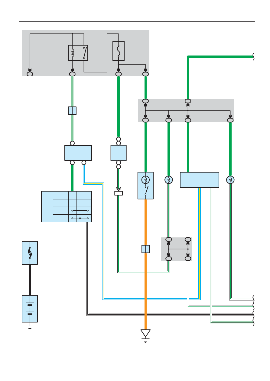
Illumination
G
W–B
W–G
W–G
H
1
5
2
3
TAILLIGHT
Relay
1G
2
1L
1
140A ALT
8
5
W
W
F10
B
Battery
C
11
B
7
TAIL
TRLY
LG
J4
3
OFF
Tail
Head
L
ight
C
ontr
o
l S
W
14
16
W–B
C 8
7. 5A
PANEL
1M
3
1E
12
G
D
D
J 9
LG
T
EL
2
1
ILL–
ILL+
(
∗
3
)(
∗
3
)
B
8
(
∗
2)
A
11
(
∗
1)
A
6
(
∗
1)
B
7
(
∗
2)
ID1
2
IG
A
A
3D
10
3A
20
9 3E
3E
10
10 3C
3A
10
2
1
1
2
ILL–
ILL+
3A
17
3E
7
3B
7
3C
7
18
12
G 3
M 5
I19
B 2
G
G
G
G
G
G
G
O
W–G
W–G
W–G
W–G
W–G
O
W–G
W–G
O 4
(A
), O 5
(B
)
B 5
(A
), B
6
(B
), B
7
(C
)
B
a
ck D
oor
P
o
w
e
r W
indow
C
ontr
o
l S
W
B
ody E
C
U
Combination SW
Fusible Link Block
G
love B
o
x L
ight
Integration Control
and Panel
Junction
Connector
Juncti
on
C
onnector
Ma
in
S
W
O
ver
head M
odul
e
13
L–
Y
A
24
MPX2
MPX+
3
MPX–
LG–
B
L–
Y
LG–B
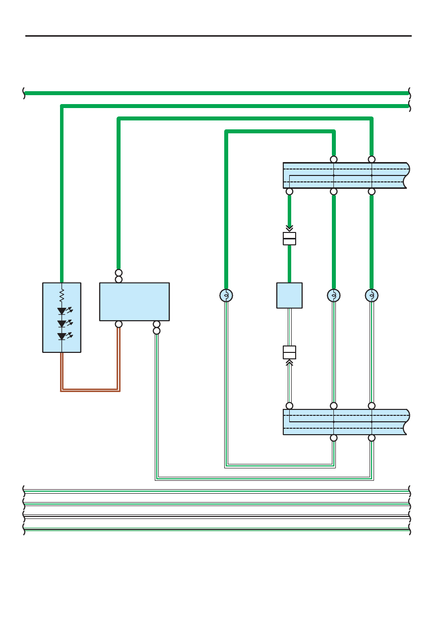
SEQUOIA (EM00Z0U)
101
G
W–B
W–G
W–G
∗
2 : w/ Sliding Roof, Rear Seat Entertainment System or Rear Seat Audio System
S
teer
ing S
W
10
1
C 9
SWG(
∗
8)
GND(
∗
9)
ILL+B(
∗
6)
C
2
(
∗
7)
A
10
(
∗
6)
D
6
(
∗
5
)
ILL–
B
5
(
∗
6)
C
12
(
∗
7)
1
5
R 2
(A
), R 3
(B
), R 4
(C
), R19
(D
)
R2
7
(D
), R30
(C
)
H1
2
ILL–
ILL+
1
5
A2
8
IF1
2
IF2
2
(
∗
3)
(
∗
4)
IF2
1
IF1
1
(
∗
3)
(
∗
4)
2
1
2
1
S 5
S 6
A
A
A
A
B
A
B
B
A
B
A
B
A
A
B
A
B
B
A
B
∗
1 : w/o Sliding Roof, Rear Seat Entertainment System and Rear Seat Audio System
G
G
W–G
W–G
W–B
W–G(
∗
5)
W–G
G(
∗
5)
G
G
G
G
G
G
G
G
BR–
W
W–G
W–G
W–G
W–G
W–G
BR–
W
ILL+(
∗
7)
(
∗
5
)
W–G
J3
9
(A
), J
4
0
(B
)
J3
9
(A
), J
4
0
(B
)
∗
3 : w/ Rear Seat Entertainment System or Rear Seat Audio System
∗
4 : w/o Rear Seat Entertainment System, Rear Seat Audio System
∗
5 : w/ Electric Modulated Air Suspension
∗
6 : 6 Speaker
∗
7 : 10 Speaker
∗
8 : w/ Navigation System
∗
9 : w/o Navigation System
A/
C Co
n
tro
l
(R
ear
H
eater
C
ontr
o
l P
anel
)
C
o
m
b
inati
on S
W
Juncti
on
C
onnector
Juncti
on
C
onnector
R
adi
o and P
layer
S
eat H
eater
S
W
Fr
ont L
H
S
eat H
eater
S
W
Fr
ont R
H
H
e
ight C
ontr
o
l S
W
R
adi
o and P
layer
w
ith D
ispl
a
y
LG–B
LG–B
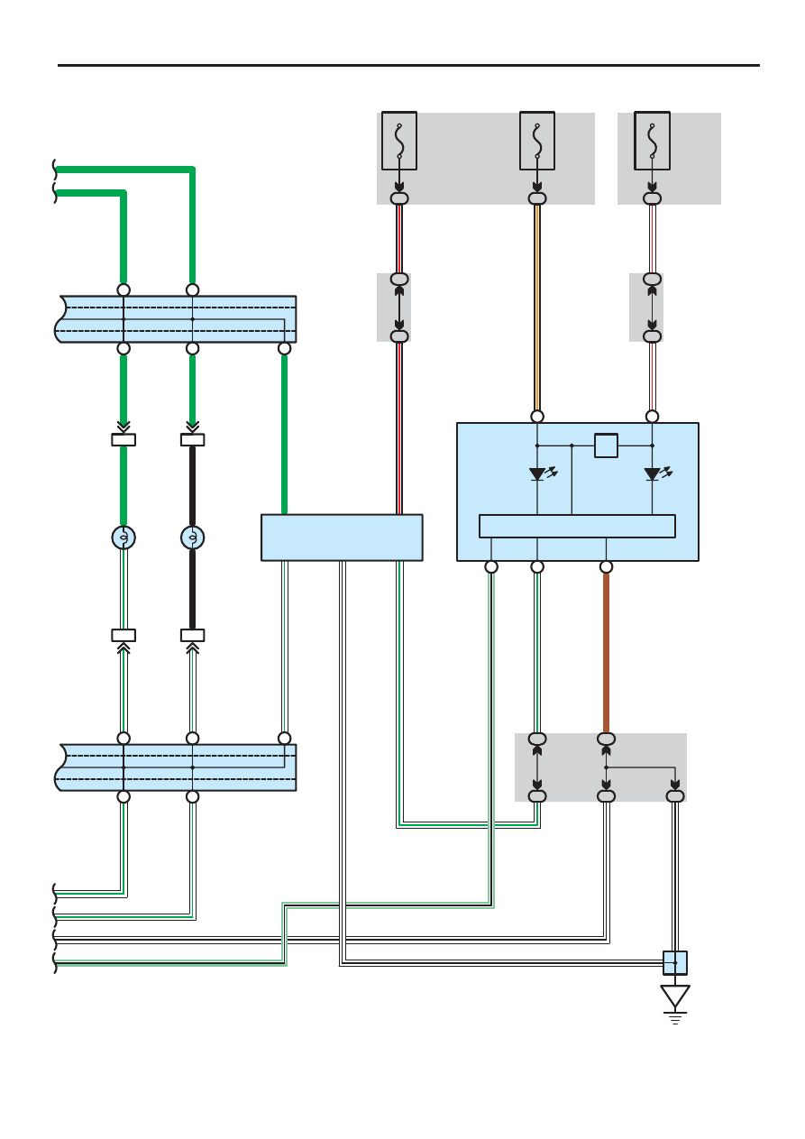
102
SEQUOIA (EM00Z0U)
Illumination
9 1F
1
2
1
2
A2
4
C 4
IE1
4
IE1
5
IE1
6
IE1
3
A
A
B
A
A
A
B
A
B
B
A
B
B
B
A
B
A
B
A
A
ILL–
T
6
4
E
5
TR
3
IE
A
IG
1
10A
ECU–IG
1F
4
3A
8
3E
8
Illu
m
in
a
tio
n
B
24
A
22
B
12
1H
8
1E
13
1D
6
1B
7
10A
IGN1
1H
11
R 6
C 5
(A
), C 6
(B
)
W–B
W–G
W–G
G
G
G
G
B–
R
B–
O
B–
R
G
G
G
G
B
W–G
B
W–G
W–G
W–G
W–B
W–G
W–G
BR
W–G
W–B
W–B
W–B
W–B
J 8
J39(A), J40(B)
J39(A), J40(B)
A
shtr
a
y Il
lu
m
inati
o
n
C
igar
ette L
ighter
Il
lu
m
inati
o
n
C
o
m
b
inati
on M
e
ter
Junction
Connector
Junction
Connector
Junction
Connector
R
heostat
LG–B
LG–
B
32 A
A
Tai
l
(C
anada
)
B
23
7. 5A
ECU–B
2C
8
W–R
W
–R
1J
3
1D
9
(BAT)
(IG)
(IG)
SEQUOIA (EM00Z0U)
103
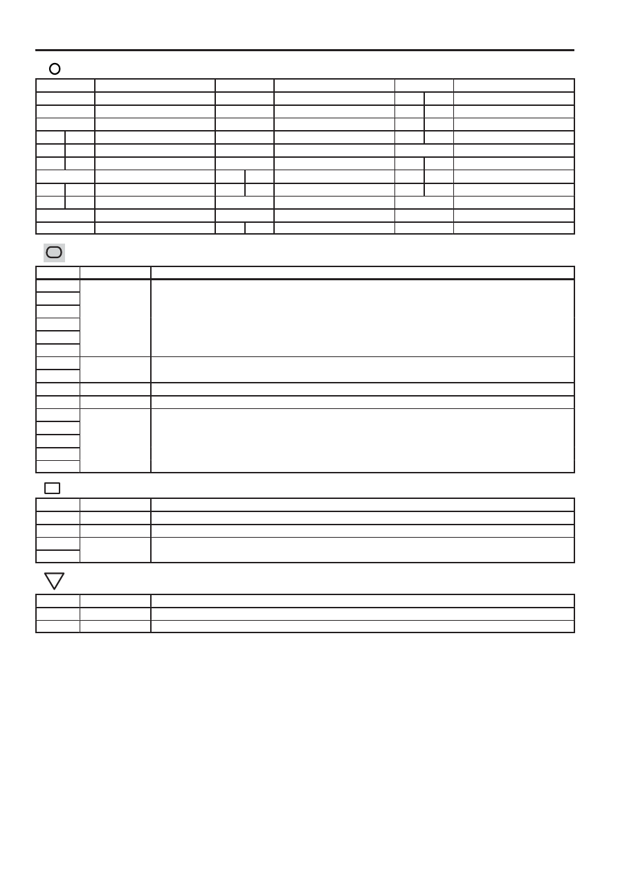
: Parts Location
Code
See Page
Code
See Page
Code
See Page
A24
42
F10
22, 40
O5
B
47
A28
42
G3
43
R2
A
45
B2
42
H12
43
R3
B
45
B5
A
42
I19
43
R4
C
45
B6
B
42
J8
44
R6
45
B7
C
42
J9
44
R19
D
45
C4
42
J39
A
44
R27
D
45
C5
A
42
J40
B
44
R30
C
45
C6
B
42
J43
44
S5
45
C8
42
M5
45
S6
45
C9
42
O4
A
47
: Junction Block and Wire Harness Connector
Code
See Page
Junction Block and Wire Harness (Connector Location)
1B
33
Cowl Wire and Instrument Panel J/B (Lower Finish Panel)
1D
33
Cowl Wire and Instrument Panel J/B (Lower Finish Panel)
1E
33
Cowl Wire and Instrument Panel J/B (Lower Finish Panel)
1F
33
Cowl Wire and Instrument Panel J/B (Lower Finish Panel)
1G
1H
1J
33
Engine Room Main Wire and Instrument Panel J/B (Lower Finish Panel)
1L
33
Engine Room Main Wire and Instrument Panel J/B (Lower Finish Panel)
1M
33
Roof Wire and Instrument Panel J/B (Lower Finish Panel)
2C
29
Engine Room Main Wire and Engine Room J/B (Engine Compartment Left)
3A
36
Cowl Wire and Sub J/B No.3 (Upper the Accelerator Pedal)
3B
36
Cowl Wire and Sub J/B No.3 (Upper the Accelerator Pedal)
3C
36
Cowl Wire and Sub J/B No.3 (Upper the Accelerator Pedal)
3D
36
Cowl Wire and Sub J/B No.3 (Upper the Accelerator Pedal)
3E
: Connector Joining Wire Harness and Wire Harness
Code
See Page
Joining Wire Harness and Wire Harness (Connector Location)
ID1
51
Cowl Wire and Roof Wire (Left Side of Instrument Panel)
IE1
51
Cigarette Lighter Wire and Cowl Wire (Instrument Panel Brace LH)
IF1
51
Console Box Wire and Cowl Wire (Rear Console)
IF2
51
Console Box Wire and Cowl Wire (Rear Console)
: Ground Points
Code
See Page
Ground Points Location
IE
51
Cowl Side Panel LH
IG
51
Cowl Side Panel RH
Нет комментариевНе стесняйтесь поделиться с нами вашим ценным мнением.
Текст