Toyota Sequoia (2005). Manual — part 981
80
SEQUOIA (EM00Z0U)
Engine Control
The engine control system utilizes a microcomputer and maintains overall control of the engine, transmission etc. An outline
of the engine control is given here.
1. Input Signals
(1) Engine coolant temp. signal circuit
The engine coolant temp. sensor detects the engine coolant temp. and has a built–in thermistor with a resistance which
varies according to the engine coolant temp. The engine coolant temp. is input into TERMINAL THW of the engine
control module as a control signal.
(2) Intake air temp. signal circuit
The intake air temp. sensor is installed in the mass air flow meter and detects the intake air temp., which is input as a
control signal to TERMINAL THA of the engine control module.
(3) Oxygen sensor signal circuit
The oxygen density in the exhaust emission is detected and is input as a control signal from the heated oxygen sensors
to TERMINALS OX1B, OX2B of the engine control module.
(4) RPM signal circuit
The camshaft position is detected by the camshaft position sensor and is input into TERMINAL G2+ of the engine
control module as a control signal. Also, the engine RPM is detected by the crankshaft position sensor and the signal is
input into TERMINAL NE+ of the engine control module.
(5) Throttle position sensor signal circuit
The throttle position sensor detects the throttle valve opening angle as a control signal, which is input into TERMINALS
VTA1, VTA2 of the engine control module.
(6) Vehicle speed circuit
The vehicle speed sensor (Combination meter) detects the vehicle speed, and the signal is input into TERMINAL SPD
of the engine control module via the combination meter.
(7) Battery signal circuit
Voltage is constantly applied to TERMINAL BATT of the engine control module. When the ignition SW is turned on, the
voltage for engine control module start up power supply is applied through the EFI relay, to TERMINALS +B, +B2 of the
engine control module. The current from the IGN1 fuse flows to TERMINAL IGSW of the engine control module, and
voltage is constantly applied to TERMINAL +BM.
(8) Intake air volume signal circuit
The intake air volume is detected by the mass air flow meter, and is input as a control signal to TERMINAL VG of the
engine control module.
(9) Stop light SW signal circuit
The stop light SW is used to detect whether the vehicle is braking or not, and the signal is input into TERMINAL STP of
the engine control module as a control signal.
(10) Starter signal circuit
To confirm whether the engine is cranking, the voltage applied to the starter motor when the engine is cranking is
detected, and is input into TERMINAL STA of the engine control module as a control signal.
(11) Engine knock signal circuit
Engine knocking is detected by the knock sensors, and is input into TERMINALS KNK1, KNK2 of the engine control
module as a control signal.
(12) A/C SW signal system
The operating voltage of the A/C magnetic clutch is detected and input in the form of a control signal to TERMINAL AC1
of the engine control module.
(13) Air fuel ratio signal system
The air fuel ratio is detected by air fuel ratio sensor and input as a control signal into TERMINALS A1A+, A2A+ of engine
control module.
System Outline
SEQUOIA (EM00Z0U)
81
2. Control System
∗
SFI system
The SFI system monitors the engine condition through the signals input from each sensors to the engine control module.
The control signal is sent to the engine control module TERMINALS #10, #20, #30, #40, #50, #60, #70 and #80 to operate
the injector (Fuel injection). The SFI system controls the fuel injection by the engine control module in response to the
driving conditions.
∗
ESA system
The ESA system monitors the engine condition through the signals input from each sensors to the engine control module.
The best ignition timing is decided according to this data and the data memorized in the engine control module. The
control signal is output to TERMINALS IGT1, IGT2, IGT3, IGT4, IGT5, IGT6, IGT7, IGT8, and these signals control the
igniter to provide the best ignition timing.
∗
Heated oxygen sensor heater control system
The heated oxygen sensor heater control system turns the heater on when the intake air volume is low (Temp. of exhaust
emission is low), and warms up the heated oxygen sensors to improve their detection performance. The engine control
module evaluates the signals from each sensors, and outputs current to TERMINALS HT1B or HT2B to control the heater.
∗
Air fuel ratio sensor heater control system
The air fuel ratio sensor heater control system turns the heater on when the intake air volume is low (Temp. of exhaust
emission is low), and warms up the air fuel ratio sensor to improve detection performance of the sensor.
The engine control module evaluates the signals from each sensor, current is output to TERMINALS HA1A and HA2A,
controlling the heater.
∗
Fuel pump control system
The engine control module supplies current to TERMINAL FPR, and controls the operation speed of the fuel pump with
the FUEL PUMP relay.
∗
ACIS
The ACIS includes a valve in the bulkhead separating the surge tank into two parts. This valve is opened and closed in
accordance with the driving conditions to control the intake manifold length in two stages, for increased engine output in all
ranges from low to high speeds.
∗
ETCS–i
The ETCS–i controls the engine output at its optimal level in accordance with the opening of the accelerator pedal, under
all driving conditions.
∗
Engine start control system
The engine control module allows power to be supplied from the TERMINAL STAR/NSW to the STA relay via park/neutral
position SW until complete combustion is confirmed by engine RPM after the detection of ignition SW ST signal by the
TERMINAL STSW.
With this arrangement, engine can be started without holding the ignition key in the ST position. At the same time, the
TERMINAL ACCR is controlled so that the engine control module turns off ACC CUT relay, shutting off power to the
accessories.
∗
VVT–i
Controls the intake camshaft to an optimal valve timing in accordance with the engine condition.
∗
Air Injection System
It is the system to improve exhaust control performance by activating catalyst at early stage, which is realized when air is
pressed and sent into the exhaust pipe forcibly by the air injection pump at starting engine in cold condition.
3. Diagnosis System
When there is a malfunction in the engine control module signal system, the malfunctioning system is recorded in the
memory. The malfunctioning system can be found by reading the code displayed on the malfunction indicator lamp.
4. Fail–Safe System
When a malfunction has occurred in any system, there is a possibility of causing engine trouble due to continued control
based on that system. In that case, the fail–safe system either controls the system using the data (Standard values)
recorded in the engine control module memory, or else stops the engine.
82
SEQUOIA (EM00Z0U)
Engine Control
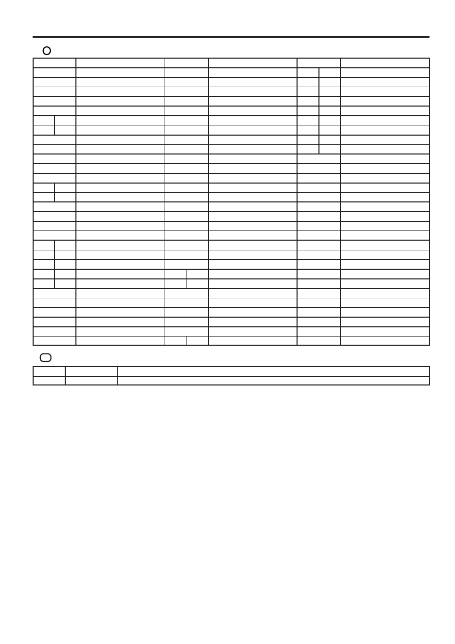
: Parts Location
Code
See Page
Code
See Page
Code
See Page
A10
40
I1
41
J45
B
44
A20
42
I2
41
J48
A
44
A37
42
I3
41
J49
B
44
A38
40
I4
41
J51
A
44
A39
40
I5
41
J52
B
44
A40
A
40
I6
41
J53
A
44
A41
B
40
I7
41
J54
B
44
A42
40
I8
41
J55
C
44
A43
40
I9
41
J56
D
44
A46
40
I10
41
K1
41
C1
40
I11
41
K2
41
C2
40
I12
41
L5
47
C5
A
42
I13
41
M1
41
C6
B
42
I14
41
P1
41
C13
40
I15
41
S1
41
C14
40
I16
41
S14
45
D6
43
I22
43
S25
45
E2
40
J2
41
T5
45
E4
A
43
J3
41
T14
41
E5
B
43
J5
41
T16
45
E6
C
43
J8
44
V1
41
E7
D
43
J14
A
44
V4
41
E8
E
43
J15
B
44
V12
41
F9
40
J16
44
V14
41
F10
22, 40
J17
44
V15
41
F19
46
J18
44
V16
41
F23
43
J42
44
V17
41
H2
40
J43
44
H4
40
J44
A
44
: Relay Blocks
Code
See Page
Relay Blocks (Relay Block Location)
2
26
Engine Room R/B No.2 (Engine Compartment Left)
SEQUOIA (EM00Z0U)
83
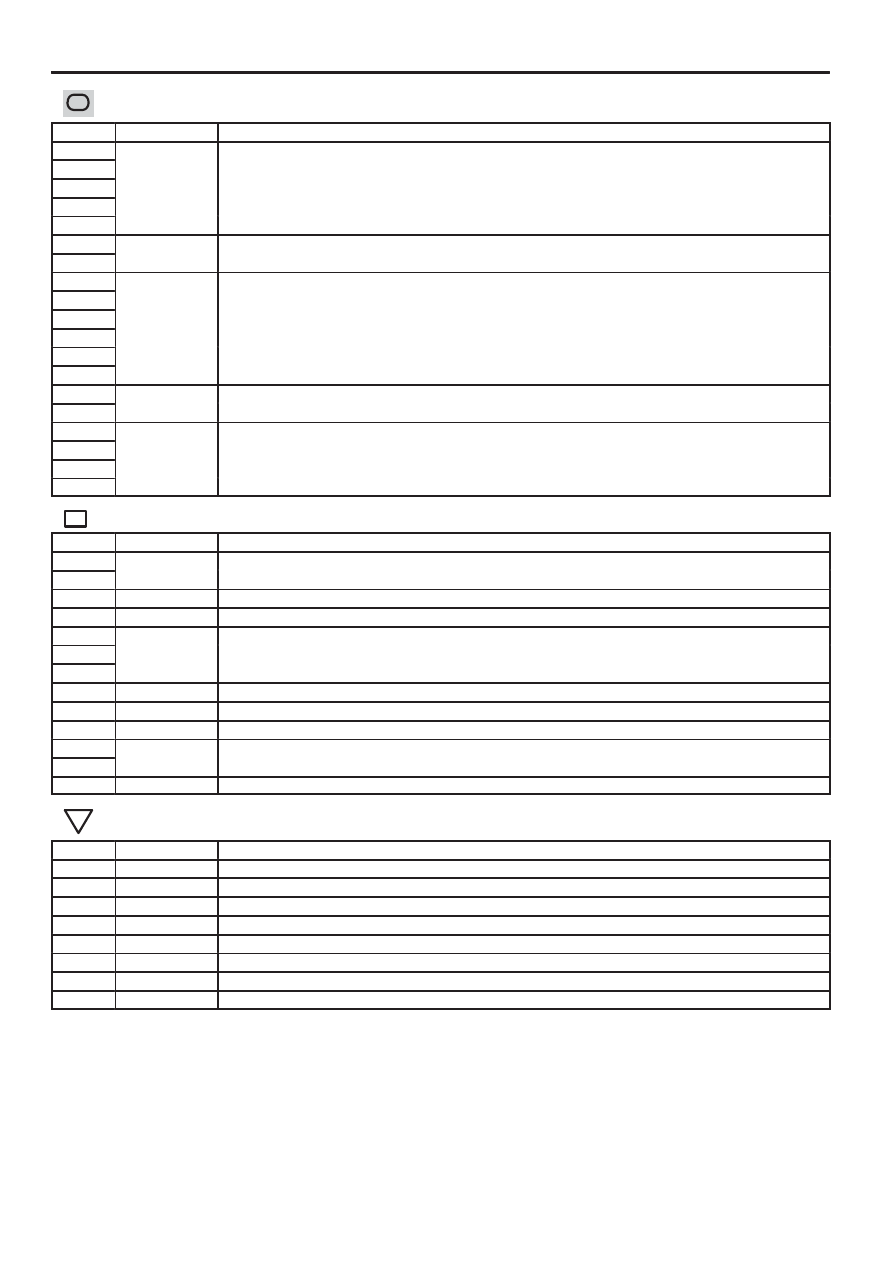
: Junction Block and Wire Harness Connector
Code
See Page
Junction Block and Wire Harness (Connector Location)
1A
33
Cowl Wire and Instrument Panel J/B (Lower Finish Panel)
1D
33
Cowl Wire and Instrument Panel J/B (Lower Finish Panel)
1E
33
Cowl Wire and Instrument Panel J/B (Lower Finish Panel)
1F
33
Cowl Wire and Instrument Panel J/B (Lower Finish Panel)
1H
1J
33
Engine Room Main Wire and Instrument Panel J/B (Lower Finish Panel)
1L
33
Engine Room Main Wire and Instrument Panel J/B (Lower Finish Panel)
2A
29
Engine Room Main Wire and Engine Room J/B (Engine Compartment Left)
2B
29
Engine Room Main Wire and Engine Room J/B (Engine Compartment Left)
2C
29
Engine Room Main Wire and Engine Room J/B (Engine Compartment Left)
2F
29
Engine Room Main Wire and Engine Room J/B (Engine Compartment Left)
2G
2H
3A
36
Cowl Wire and Sub J/B No.3 (Upper the Accelerator Pedal)
3B
36
Cowl Wire and Sub J/B No.3 (Upper the Accelerator Pedal)
4A
38
Cowl Wire and Sub J/B No.4 (Upper the Accelerator Pedal)
4B
38
Cowl Wire and Sub J/B No.4 (Upper the Accelerator Pedal)
4D
38
Cowl Wire and Sub J/B No.4 (Upper the Accelerator Pedal)
4E
: Connector Joining Wire Harness and Wire Harness
Code
See Page
Joining Wire Harness and Wire Harness (Connector Location)
EB4
50
Engine No.2 Wire and Engine Wire (Near the Starter)
EB5
50
Engine No.2 Wire and Engine Wire (Near the Starter)
EC1
50
Engine No.2 Wire and Differential Wire (Near the Transmission)
ED2
50
Engine No.2 Wire and Engine Room Main Wire (Under the Engine Room J/B)
IA1
51
Engine Room Main Wire and Cowl Wire (Cowl Side Panel LH)
IA4
51
Engine Room Main Wire and Cowl Wire (Cowl Side Panel LH)
IA5
51
Engine Room Main Wire and Cowl Wire (Cowl Side Panel LH)
IG4
51
Engine Wire and Cowl Wire (Right Side of Instrument Panel)
IJ3
51
Floor No.1 Wire and Cowl Wire (Right Kick Panel)
IL2
51
Engine Room Main Wire and Cowl Wire (Cowl Side Panel RH)
BB1
52
Frame Wire and Floor No.1 Wire (Under the Front Passenger’s Seat)
BB2
52
Frame Wire and Floor No.1 Wire (Under the Front Passenger’s Seat)
BN1
52
Frame No.2 Wire and Frame Wire (Left Side of No.6 Crossmember)
: Ground Points
Code
See Page
Ground Points Location
EB
50
Rear Left Side of Cylinder Head
EC
50
Front Left Side of Cylinder Head
ED
50
Front Fender Apron LH
EN
50
Left Side of Cylinder Block
IE
51
Cowl Side Panel LH
IG
51
Cowl Side Panel RH
BI
52
Rear Side No.4 Crossmember of Side Rail LH
BK
52
Center Pillar RH
Нет комментариевНе стесняйтесь поделиться с нами вашим ценным мнением.
Текст