Toyota Sequoia (2005). Manual — part 580
I28665
(Shielded)
R2
G2
B2
VR2
VG2
(Shielded)
R21
16
15
14
12
11
24
16
13
14
15
17
18
R21
R21
R21
IF4
ID2
R21
R
G
B
VR
VG
B
B
B
B
B
B
B
B
15
IF4
14
IF4
12
IF4
11
IF4
23
ID2
22
ID2
20
ID2
19
ID2
(Shielded)
B
B
B
B
R25
Television Display Assy
Multi–display Controller Sub–assy
13
21
13
16
IF4
ID2
R21
SYNC
B
B
B
SYN2
–
DIAGNOSTICS
REAR SEAT ENTERTAINMANT SYSTEM
DI–2115
2309
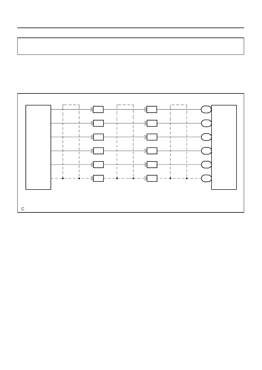
Display signal circuit (Multi–display controller sub–assy – Televi-
sion display assy)
CIRCUIT DESCRIPTION
This is the display signal circuit from the multi–display controller sub–assy to the television display assy.
WIRING DIAGRAM
DIDB7–01
I28616
Television Display Assy:
Multi–display Controller Sub–assy:
VG
VR
SYNC
VG2
VR2
SYN2
R25
R21
R
G
B
R2
G2
B2
DI–2116
–
DIAGNOSTICS
REAR SEAT ENTERTAINMANT SYSTEM
2310
INSPECTION PROCEDURE
1
Display check mode (Color bar check).
CHECK:
Enter display check mode (See page
).
Start the diagnosis system and perform the display color bar check in display check mode.
OK:
The check result is normal.
OK
Adjust display color.
NG
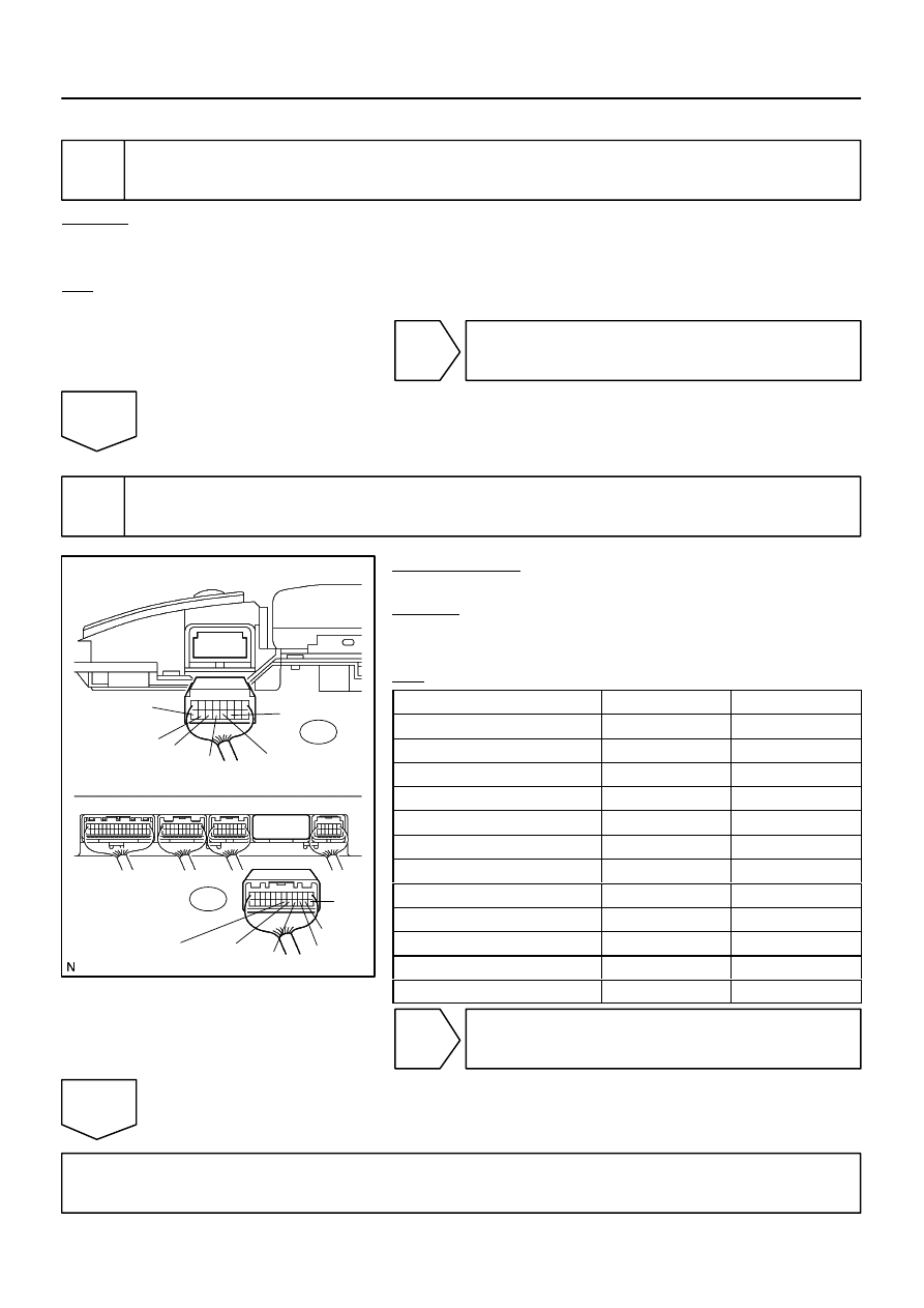
2
Check harness and connector (Multi–display controller sub–assy – Television
display assy).
PREPARATION:
Disconnect the R21 and R25 connectors.
CHECK:
Measure the resistance according to the value(s) in the table
below.
OK:
Symbol (Tester connection)
Condition
Specified condition
VG (R25–11) – VG2 (R21–18)
Always
Below 1
Ω
VR (R25–12) – VR2 (R21–17)
Always
Below 1
Ω
SYNC (R25–13) – SYN2 (R21–16)
Always
Below 1
Ω
B (R25–14) – B2 (R21–15)
Always
Below 1
Ω
G (R25–15) – G2 (R21–14)
Always
Below 1
Ω
R (R25–16) – R2 (R21–13)
Always
Below 1
Ω
VG (R25–11)– Body ground
Always
10 k
Ω
or higher
VR (R25–12) – Body ground
Always
10 k
Ω
or higher
SYNC (R25–13) – Body ground
Always
10 k
Ω
or higher
B (R25–14) – Body ground
Always
10 k
Ω
or higher
G (R25–15) – Body ground
Always
10 k
Ω
or higher
R (R25–16) – Body ground
Always
10 k
Ω
or higher
NG
Repair or replace harness or connector.
OK
Proceed to next circuit inspection shown in problem symptoms table (See page
I28666
Multi–display
Controller Sub–assy
NTS2
SGN2
SG9
R22
8
R22
9
R22
10
BR
BR
NTSC
S.GND
SLD
3
2
1
(Shielded)
D23
Disc Player Controller
–
DIAGNOSTICS
REAR SEAT ENTERTAINMANT SYSTEM
DI–2117
2311
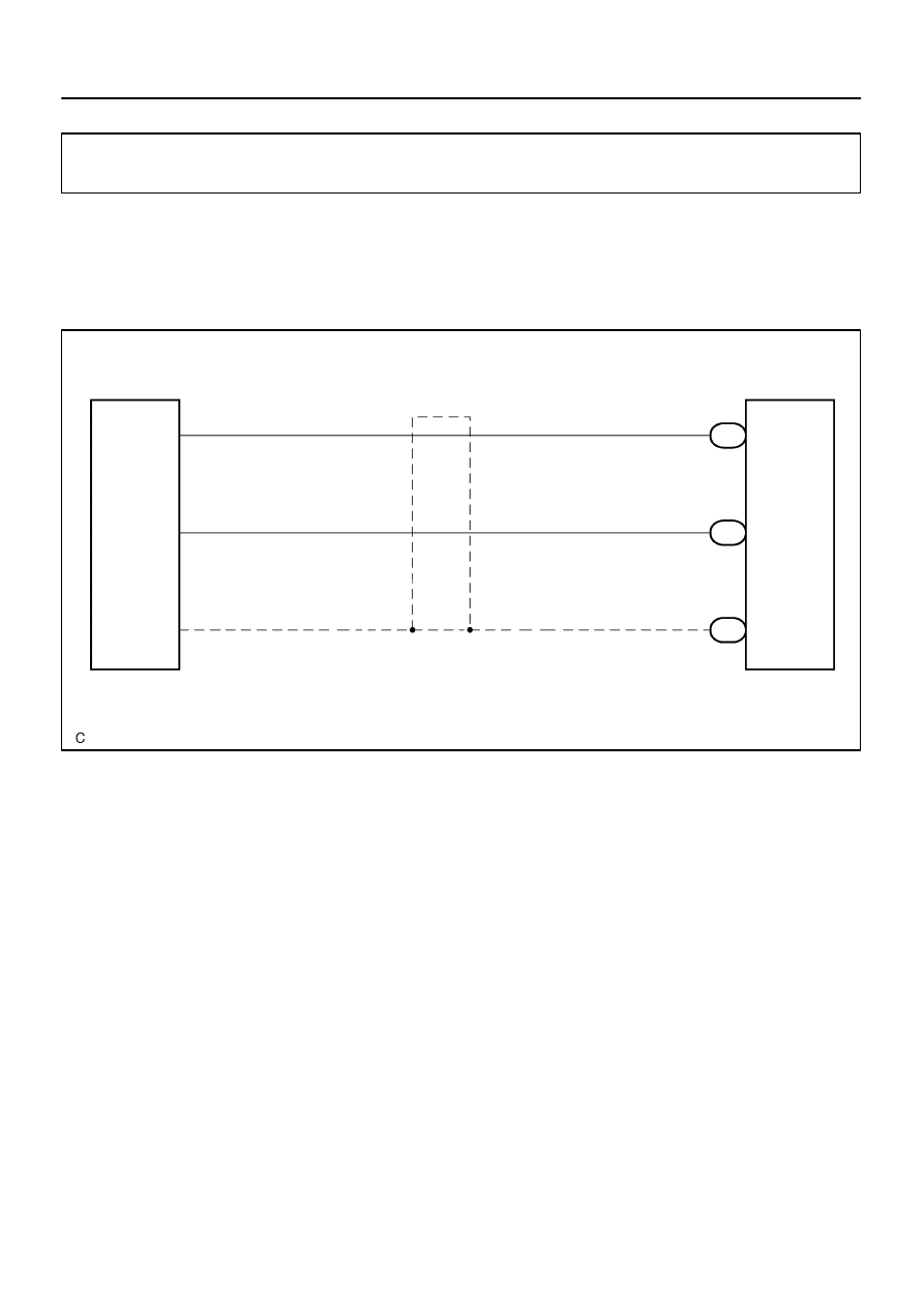
Display signal circuit (Multi–display controller sub–assy – Disc
player controller)
CIRCUIT DESCRIPTION
This is the display signal circuit from the disc player controller to the multi–display controller sub–assy.
WIRING DIAGRAM
DIDB8–01
I28326
Disc Player Controller:
Multi–display Controller Sub–assy:
SLD
S.GND
NTSC
NTS2
SGN2
SG9
D23
R22
DI–2118
–
DIAGNOSTICS
REAR SEAT ENTERTAINMANT SYSTEM
2312
INSPECTION PROCEDURE
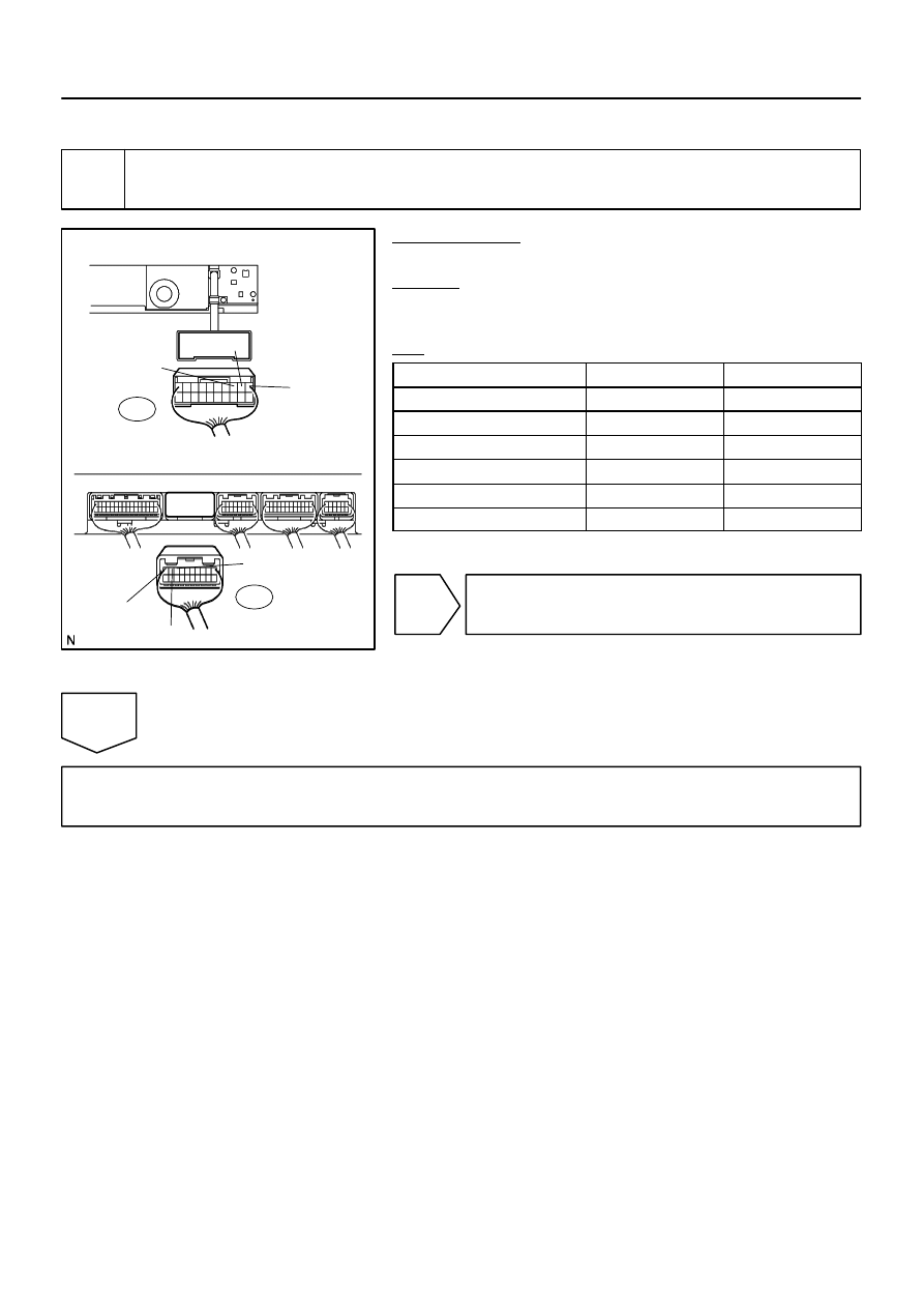
1
Check harness and connector (Multi–display controller sub–assy – Disc player
controller).
PREPARATION:
Disconnect the R22 and D23 connectors.
CHECK:
Measure the resistance according to the value(s) in the table
below.
OK:
Symbol (Tester connection)
Condition
Specified condition
NTSC (D23–3) – NTS2 (R22–8)
Always
Below 1
Ω
S.GND (D23–2)– SGN2 (R22–9)
Always
Below 1
Ω
SLD (D23–1)– SG9 (R22–10)
Always
Below 1
Ω
NTSC (D23–3) – Body ground
Always
10 k
Ω
or higher
S.GND (D23–2) – Body ground
Always
10 k
Ω
or higher
SLD (D23–1) – Body ground
Always
10 k
Ω
or higher
NG
Repair or replace harness or connector.
OK
Proceed to next circuit inspection shown in problem symptoms table (See page
Нет комментариевНе стесняйтесь поделиться с нами вашим ценным мнением.
Текст