Toyota Sequoia (2005). Manual — part 76
A21226
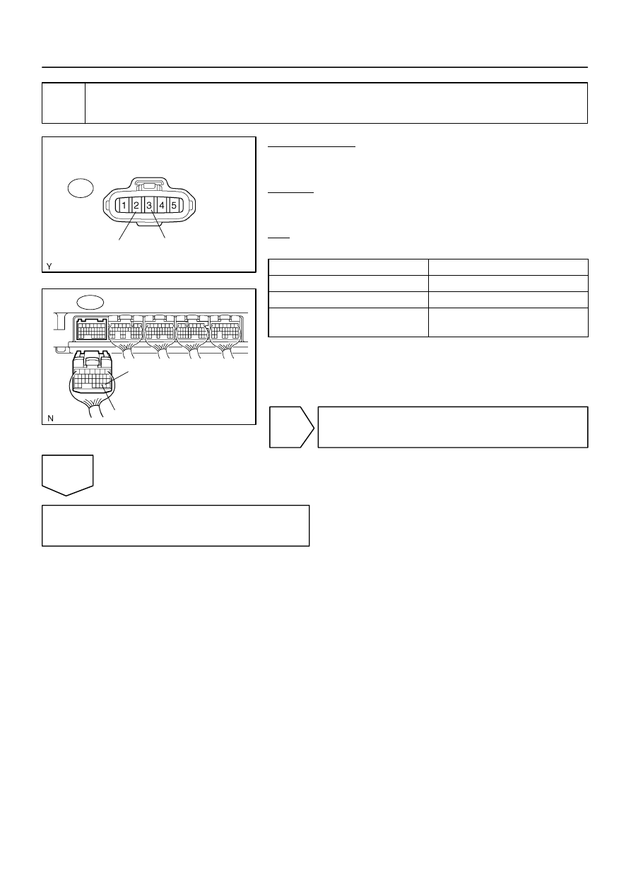
Wire Harness Side:
Mass Air Flow Meter Connector
M1
E2G
VG
B17412
E8
ECM Connector
E2G
VG
–
DIAGNOSTICS
ENGINE
DI–107
301
4
Check for open and short in harness and connector between mass air flow meter
and ECM.
PREPARATION:
(a)
Disconnect the M1 mass air flow meter connector.
(b)
Disconnect the E8 ECM connector.
CHECK:
Check the resistance between the wire harness side connec-
tors.
OK:
Standard:
Tester Connection
Specified Condition
VG (M1–3) – VG (E8–30)
Below 1
Ω
E2G (M1–2) – E2G (E8–29)
Below 1
Ω
VG (M1–3) or VG (E8–30) –
Body ground
10 k
Ω
or higher
NG
Repair or replace harness or connector.
OK
Replace mass air flow meter.
A21375
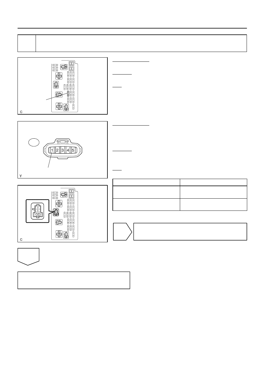
Engine Room J/B:
EFI
No. 2 Fuse
A21226
Wire Harness Side:
Mass Air Flow Meter Connector
M1
+B
A21376
Engine Room J/B:
EFI Relay
DI–108
–
DIAGNOSTICS
ENGINE
302
5
Check for open and short in harness and connector between mass air flow meter
and EFI relay.
PREPARATION:
Remove the EFI No. 2 fuse from the engine room J/B.
CHECK:
Check the resistance in the EFI No. 2 fuse.
OK:
Standard:
Below 1
Ω
PREPARATION:
(a)
Install the EFI No. 2 fuse.
(b)
Disconnect the M1 mass air flow meter connector.
(c)
Remove the EFI relay from the engine room J/B.
CHECK:
Check the resistance between the wire harness side connec-
tors.
OK:
Standard:
Tester Connection
Specified Condition
+B (M1–1) – Engine Room J/B (EFI
relay terminal 1)
Below 1
Ω
+B (M1–1) or Engine room J/B (EFI relay
terminal 1) – Body ground
10 k
Ω
or higher
NG
Repair or replace harness or connector.
OK
Check ECM power source circuit
(See page
B17412
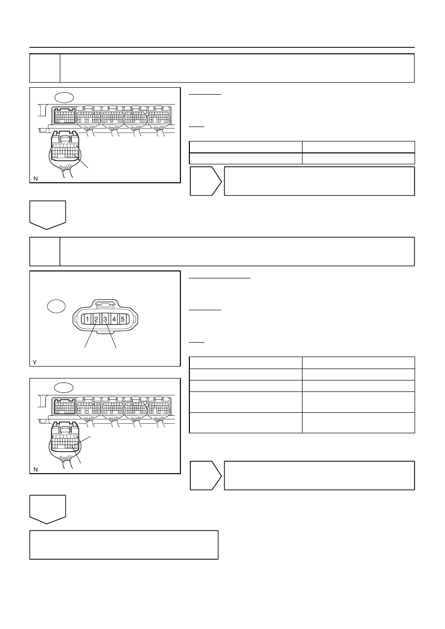
E2G
E8 ECM Connector
A21226
Wire Harness Side:
Mass Air Flow Meter Connector
M1
VG
E2G
B17412
E8
ECM Connector
E2G
VG
–
DIAGNOSTICS
ENGINE
DI–109
303
6
Check continuity between terminal E2G of ECM connector and body ground.
CHECK:
Check the resistance between terminal of the E8 ECM connec-
tor and body ground.
OK:
Standard:
Tester Connection
Specified Condition
E2G (E8–29) – Body ground
Below 1
Ω
NG
Replace ECM (See page
OK
7
Check for open in harness and connector between mass air flow meter and ECM.
PREPARATION:
(a)
Disconnect the M1 mass air flow meter connector.
(b)
Disconnect the E8 ECM connector.
CHECK:
Check the resistance between the wire harness side connec-
tors.
OK:
Standard:
Tester Connection
Specified Condition
VG (M1–3) – VG (E8–30)
Below 1
Ω
E2G (M1–2) – E2G (E8–29)
Below 1
Ω
VG (M1–3) or VG (E8–30) –
Body ground
10 k
Ω
or higher
E2G (M1–2) or E2G (E8–29) –
Body ground
10 k
Ω
or higher
NG
Repair or replace harness or connector.
OK
Replace mass air flow meter.
DI–110
–
DIAGNOSTICS
ENGINE
304
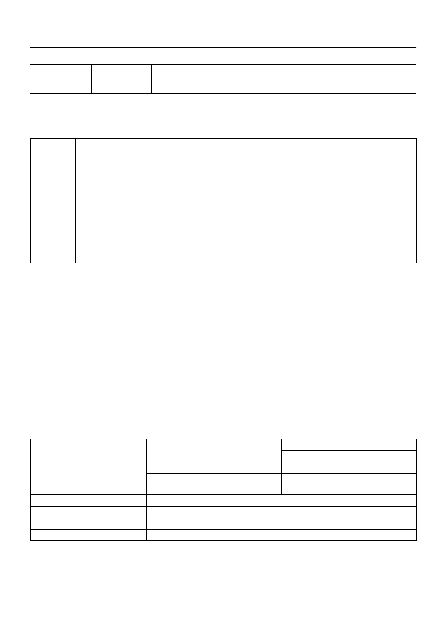
DTC
P0101
Mass or Volume Air Flow Circuit Range/
Performance Problem
CIRCUIT DESCRIPTION
Refer to DTC P0100, P0102 and P0103 on page
.
DTC No.
DTC Detecting Condition
Trouble Area
P0101
After engine is warmed up, conditions (a), (b), (c) and (d) con-
tinue for more than 10 seconds:
(2 trip detection logic)
(a) Throttle valve fully closed
(b) Voltage output of the mass air flow meter is more than 2.2
V.
(c) Engine coolant temperature is more than 70
°
C (158
°
F).
(d) Engine speed is less than 2,000 rpm.
Mass air flow meter
Conditions (a), (b) and (c) continue for more than 10 seconds
at engine speed: (2 trip detection logic)
(a) Engine speed is more than 300 rpm.
(b) Voltage output of the mass air flow meter is less than 1.0 V.
MONITOR DESCRIPTION
The MAF (Mass Air Flow) meter helps the ECM calculate the amount of air flowing through the throttle valve.
The ECM uses this information to determine the fuel injection time and provide a proper air fuel ratio. Inside
the MAF meter, there is a heated platinum wire exposed to the flow of intake air. By applying a specific current
to the wire, the ECM heats this wire to a given temperature. The flow of incoming air cools the wire and an
internal thermistor, affecting their resistance. To maintain a constant current value, the ECM varies the volt-
age applied to these components in the MAF meter. The voltage level is proportional to the air flow through
the MAF meter. The ECM interprets this voltage as the intake air amount. If there is a defect in the MAF meter
or an open or short circuit, the voltage level will deviate outside the normal operating range. The ECM inter-
prets this deviation as a defect in the MAF meter and sets a DTC.
Example:
If the voltage is more than 2.2 V at idle or less than 1.0 V at idle OFF, the ECM interprets this as a defect
in the MAF meter and sets a DTC.
MONITOR STRATEGY
R l t d DTC
P0101
Mass air flow meter rationality (Low voltage)
Related DTCs
P0101
Mass air flow meter rationality (High voltage)
Main sensors/components
Mass air flow meter
Required sensors/components
Related sensors/components
Engine speed sensor, Engine coolant tempera-
ture sensor, Throttle position sensor
Frequency of operation
Continuous
Duration
10 sec.
MIL operation
2 driving cycles
Sequence of operation
None
DI3HM–13
Нет комментариевНе стесняйтесь поделиться с нами вашим ценным мнением.
Текст