Toyota Sequoia (2005). Manual — part 77

–
DIAGNOSTICS
ENGINE
DI–111
305
TYPICAL ENABLING CONDITIONS
It
Specification
Item
Minimum
Maximum
The monitor will run whenever this DTC is
not present
See page
High voltage:
Engine speed
–
2,000 rpm
MAF meter voltage
–
4.9 V
Engine coolant temperature
70
C (158
F)
–
Low voltage:
Engine speed
300 rpm
–
MAF meter voltage
0.2 V
–
Fuel cut
OFF
TYPICAL MALFUNCTION THRESHOLDS
Detection Criteria
Threshold
Mass air flow meter voltage (High voltage)
More than 2.2 V (varies with throttle position sensor voltage)
Mass air flow meter voltage (Low voltage)
Less than 1.0 V (varies with throttle position sensor voltage)

DI–112
–
DIAGNOSTICS
ENGINE
306
INSPECTION PROCEDURE
HINT:
Read freeze frame data using
the hand−held tester
. Freeze frame data records the engine conditions when
a malfunction is detected. When troubleshooting, freeze frame data can help determine if the vehicle was
running or stopped, if the engine was warmed up or not, if the air–fuel ratio was lean or rich, as well as other
data from the time when a malfunction occurred.
1
Are there any other codes (besides DTC P0101) being output?
PREPARATION:
(a)
Connect the hand–held tester to the DLC3.
(b)
Turn the ignition switch ON and push the hand–held tester main switch ON.
(c)
When using hand–held tester, enter the following menu: DIAGNOSIS/ENHANCED OBD II/DTC INFO/
CURRENT CODES.
CHECK:
Read the DTC using the hand–held tester.
RESULT:
Display (DTC output)
Proceed to
”P0101” and other DTCs
A
Only P0101
B
HINT:
If any other codes besides P0101 are output, perform the troubleshooting for those codes first.
B
Replace mass air flow meter.
A
Go to relevant DTC chart (See page
– 20
0
20
40
60
80
100
(– 4)
32
68
104
140
176
212
30
20
10
5
3
2
1
0.5
0.3
0.2
0.1
A21047
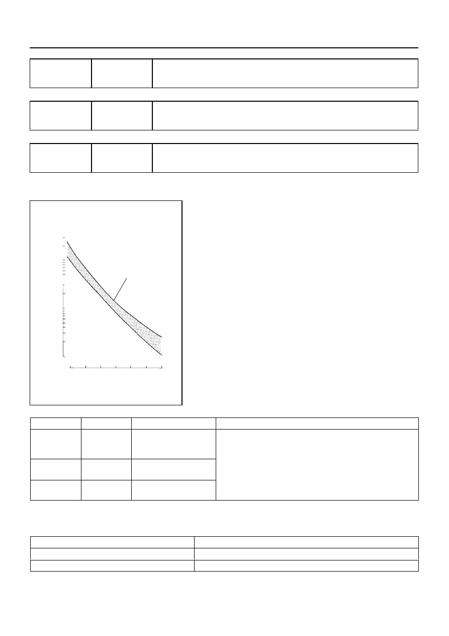
Acceptable
(Fig.1)
Resistance K
Ω
Temp.
C (
F)
–
DIAGNOSTICS
ENGINE
DI–113
307
DTC
P0110
Intake Air Temperature Circuit
DTC
P0112
Intake Air Temperature Circuit Low Input
DTC
P0113
Intake Air Temperature Circuit High Input
CIRCUIT DESCRIPTION
The intake air temperature (IAT) sensor, mounted on the mass
air flow (MAF) meter, monitors the intake air temperature. The
IAT sensor has a thermistor that varies its resistance depending
on the temperature of the intake air. When the air temperature
is low, the resistance in the thermistor increases. When the tem-
perature is high, the resistance drops. The resistance varies as
voltage changes to the ECM terminal.
(See Fig. 1).
The intake air temperature sensor is connected to the ECM
(See below ). The 5 V power source voltage in the ECM is ap-
plied to the intake air temperature sensor from terminal THA
(THAR) via resistor R.
That is, the resistor R and the intake air temperature sensor are
connected in series. When the resistance value of the intake air
temperature sensor changes in accordance with changes in the
intake air temperature, the voltage at terminal THA (THAR) also
changes. Based on this signal, the ECM increases the fuel in-
jection volume to improve the driveability during cold engine op-
eration.
DTC No.
Proceed to
DTC Detection Condition
Trouble Area
P0110
Step 1
Open or short in intake air
temperature sensor circuit for
0.5 sec.
Open or short in intake air temperature sensor circuit
P0112
Step 4
Short in intake air tempera-
ture sensor circuit for 0.5 sec.
Open or short in intake air temperature sensor circuit
Intake air temperature sensor (built in mass air flow meter)
ECM
P0113
Step 2
Open in intake air tempera-
ture sensor circuit for 0.5 sec.
ECM
HINT:
After confirming DTC ”P0110, P0112 or P0113”, use the hand–held tester to confirm the intake air tempera-
ture in the ”DIAGNOSIS / ENHANCED OBD II / DATA LIST / ALL”.
Temperature Displayed
Malfunction
–40
°
C (–40
°F)
Open circuit
140
°
C (284
°F) or more
Short circuit
DI3HN–13

DI–114
–
DIAGNOSTICS
ENGINE
308
MONITOR DESCRIPTION
The ECM monitors the sensor voltage and uses this value to calculate the intake air temperature. When the
sensor output voltage deviates from the normal operating range, the ECM interprets this as a fault in the IAT
(Intake Air Temperature) sensor and sets a DTC.
Example:
When the sensor voltage output is equal to –40
C (–40
F), or more than 140
C (284
F).
MONITOR STRATEGY
P0110
Intake air temperature sensor range check
(Fluttering)
Related DTCs
P0112
Intake air temperature sensor range check
(Low resistance)
P0113
Intake air temperature sensor range check
(High resistance)
Required sensors/components
Intake air temperature sensor
Frequency of operation
Continuous
Duration
0.5 sec.
MIL operation
Immediate
Sequence of operation
None
TYPICAL ENABLING CONDITIONS
The monitor will run whenever these
DTCs are not present
See page
The typical enabling condition is not avail-
able
–
TYPICAL MALFUNCTION THRESHOLDS
Detection Criteria
Threshold
P0110:
Intake air temperature sensor resistance
(Intake air temperature)
Less than 98.5
Ω,
or more than 156 k
Ω
(More than 140
C (284
F), or less than –40
C (–40
F)
P0112:
Intake air temperature sensor resistance
(Intake air temperature)
Less than 98.5
Ω
(More than 140
C (284
F))
P0113:
Intake air temperature sensor resistance
(Intake air temperature)
More than 156 k
Ω
(Less than –40
C (–40
F))
COMPONENT OPERATING RANGE
Parameter
Standard Value
Intake air temperature sensor resistance
98.5
Ω
(140
C (284
F)) to 156 k
Ω
(–40
C (–40
F))
Нет комментариевНе стесняйтесь поделиться с нами вашим ценным мнением.
Текст