Toyota Sequoia (2005). Manual — part 459
I28569
C5–3
C5–28
Combination Meter:
I28570
C6–12
C6–24
C6–23
Combination Meter:
–
DIAGNOSTICS
COMBINATION METER SYSTEM
DI–1631
1825
2
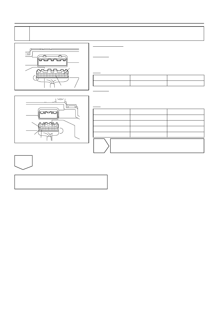
Inspect combination meter (Power source).
PREPARATION:
Disconnect the combination meter connectors.
CHECK:
Measure the resistance according to the value(s) in the table
below.
OK:
Terminal No
Condition
Specified condition
C6–12 – Body ground
Always
Below 1
Ω
CHECK:
Measure the voltage according to the value(s) in the table be-
low.
OK:
Terminal No
Condition
Specified condition
C6–23 – Body ground
Always
10 to 14 V
C5–28 – Body ground
Ignition switch ON
10 to 14 V
C6–24 – Body ground
Ignition switch ON
10 to 14 V
C5–3 – Body ground
Ignition switch ST
10 to 14 V
NG
Repair or replace harness or connector.
OK
Replace combination meter
(See page
).
I28558
C6
12
W–B
Battery
A
W
5
8
BR
IE
Combination Meter
W–L
I18
Ignition SW
2
1
AM1
IG1
B–Y
W
Instrument Panel J/B
AM1
2
1
4
7
6
1
6
9
1C
1C
1D
1E
1L
1F
R–L
R–L
Sub J/B No. 3
3B
3A
5
15
C5
24
C6
10
R–L
Y–R
Y
Y–R
Y
1
3
2
3
19
26
IG4
IG4
IG4
GAUGE
B
V1
Vehicle Speed Sensor
(Combination Meter)
F10
Fusible Link Block
J8
J/C
DI–1632
–
DIAGNOSTICS
COMBINATION METER SYSTEM
1826
Malfunction in speedometer
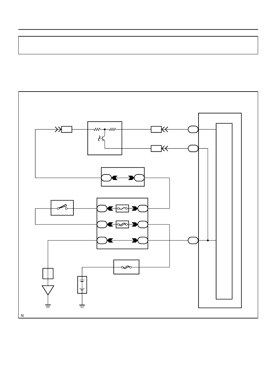
CIRCUIT DESCRIPTION
The speedometer detects vehicle speed based on a 4–pulse signal from the vehicle speed sensor.
WIRING DIAGRAM
DID8Z–01
–
DIAGNOSTICS
COMBINATION METER SYSTEM
DI–1633
1827
INSPECTION PROCEDURE
HINT:
Start the inspection from step 1 when using the hand–held tester and start from step 3 when not using the
hand–held tester.
1
Perform active test by hand–held tester.
PREPARATION:
(a)
Connect the hand–held tester to the DLC3.
(b)
Turn the ignition switch ON, and push the hand–held tester main switch ON.
CHECK:
From the display on the tester, perform the ”ACTIVE TEST”.
METER:
Item
Test Details
Diagnostic Note
SPEED METER
0 / 40 (24) / 80 (48) / 120 (72) / 160 (96) /
200 (120) km/h (mph)
The needle position should be within the accept-
able tolerance.
OK:
Speedometer readings change according to hand–held tester operation.
NG
Replace combination meter
(See page
).
OK
2
Read value of hand–held tester.
PREPARATION:
(a)
Connect the hand–held tester to the DLC3.
(b)
Turn the ignition switch ON, and push the hand–held tester main switch ON.
CHECK:
Operate the hand–held tester according to the steps on the display and select ”DATA LIST”.
METER:
Item
Measurement Item/
Range (Display)
Normal Condition
Diagnostic Note
SPEED METER
Vehicle Speedometer /
Min.: 0 km/h (0 mph)
Max.: 255 km/h (158 mph)
Almost the same as actual vehicle
speed (When driving)
OK:
Vehicle speed displayed on the tester is almost the same as the actual vehicle speed.
OK
Replace combination meter
(See page
).
NG
N02332
1
2
3
DI–1634
–
DIAGNOSTICS
COMBINATION METER SYSTEM
1828
3
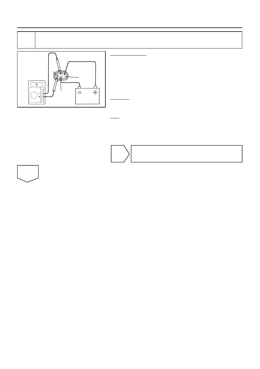
Inspect vehicle speed sensor.
PREPARATION:
(a)
Disconnect the vehicle speed sensor connector.
(b)
Connect the positive (+) lead from the battery to terminal
1 and the negative (–) lead to terminal 2.
(c)
Connect the positive (+) lead from the tester to terminal
3 and the negative (–) lead to terminal 2.
(d)
Rotate the shaft.
CHECK:
Check that voltage between terminals 2 and 3 changes from
approx. 0 V to16 V or more.
OK:
Voltage changes from approx. 0 V to 16 V
HINT:
The voltage should change 4 times for every revolution of the
speed sensor shaft.
NG
Replace vehicle speed sensor.
OK
Нет комментариевНе стесняйтесь поделиться с нами вашим ценным мнением.
Текст