Toyota Sequoia (2005). Manual — part 457
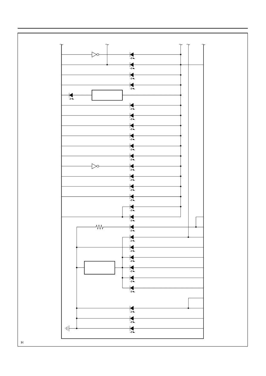
I27707
C6–21
C6–8
(*4) C5–15
C5–18
C5–2
C5–14
C5–19
C5–13
C6–1
C6–2
C6–3
C5–20
ABS
CHARGE
A/T OIL TEMP
CHECK E/G
4LO
O/D OFF
A/T L
WASHER
SLIP
VSC OFF
VSC TRAC
4HI
CRUISE
ONE STEP
DIMMER
C6–24
C6–5
C6–6
C6–4
C5–40
TIRE PRS
CTR DIFF LOCK
RSCA OFF
SECURITY
P
R
N
C5–16
C5–17
C5–34
C5–35
C5–36
C5–37
C5–38
C5–39
C6–17 (*5)
C6–18 (*6)
C5–33
C6–19
TURN (L)
TURN (R)
BEAM
3
2
D
*4: 4WD *5: w/o Daytime Running Light *6: w/ Daytime Running Light
ONE STEP
DIMMER
RSCA OFF
–
DIAGNOSTICS
COMBINATION METER SYSTEM
DI–1623
1817
Wire harness side
1
2
3
4
5
6
13
14
15
16
17
18
19
20
21
22
23
24
25
26
27
28
29
30
31
32
33
34
35
36
37
38
39
40
1
2
3
4
5
8
6
10
11
12
13
14
15
16
17
18
19
21
23
24
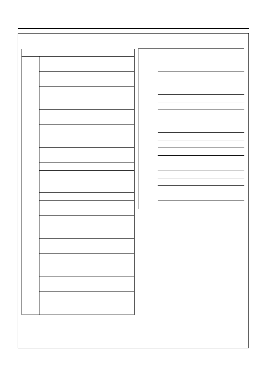
Terminal No.
Translate ECU
ECM
STA Fuse
Front Seat Inner Belt LH (Buckle Switch)
Overhead Module (Garage Door Opener)
Overhead Module (Garage Door Opener)
Washer Level Sensor
ECM
ECM (*1)
Transponder Key Computer
Body ECU
ECM
ECM
Tire Pressure Monitor ECU
Injector No. 1
Light Control Rheostat
ECM
Speed Sensor
4P OUT (Other Parts)
Fuel Sender Gauge
Oil Pressure Sender Gauge
IGN Fuse
Airbag Sensor Assembly
Memory Seat ECU and SW (*2)
Back Door ECU
Integration Control and Panel
Turn Signal Flasher Relay
Park/Neutral Position Switch
Airbag Sensor Assembly
Translate ECU
Translate ECU
Skid Control ECU
4WD Control ECU
Alternator
Speed Sensor
Fuel Sender Gauge
Ground
Suspension Control ECU
Body ECU (*4)
Body ECU (*3)
Turn Signal Flasher Relay
Skid Control ECU
ECU–B Fuse
IGN1 Fuse
Connectors:
Terminal No.
Wire harness side
C5
C6
4WD Control ECU
4WD Control ECU
Suspension Control ECU
Suspension Control ECU
Suspension Control ECU
*1: 4WD
*2: w/ Driving Position Memory
*3: w/ Daytime Running Light
*4: w/o Daytime Running Light
Park/Neutral Position Switch
Park/Neutral Position Switch
Park/Neutral Position Switch
Park/Neutral Position Switch
Park/Neutral Position Switch
DI–1624
–
DIAGNOSTICS
COMBINATION METER SYSTEM
1818
DID8W–01
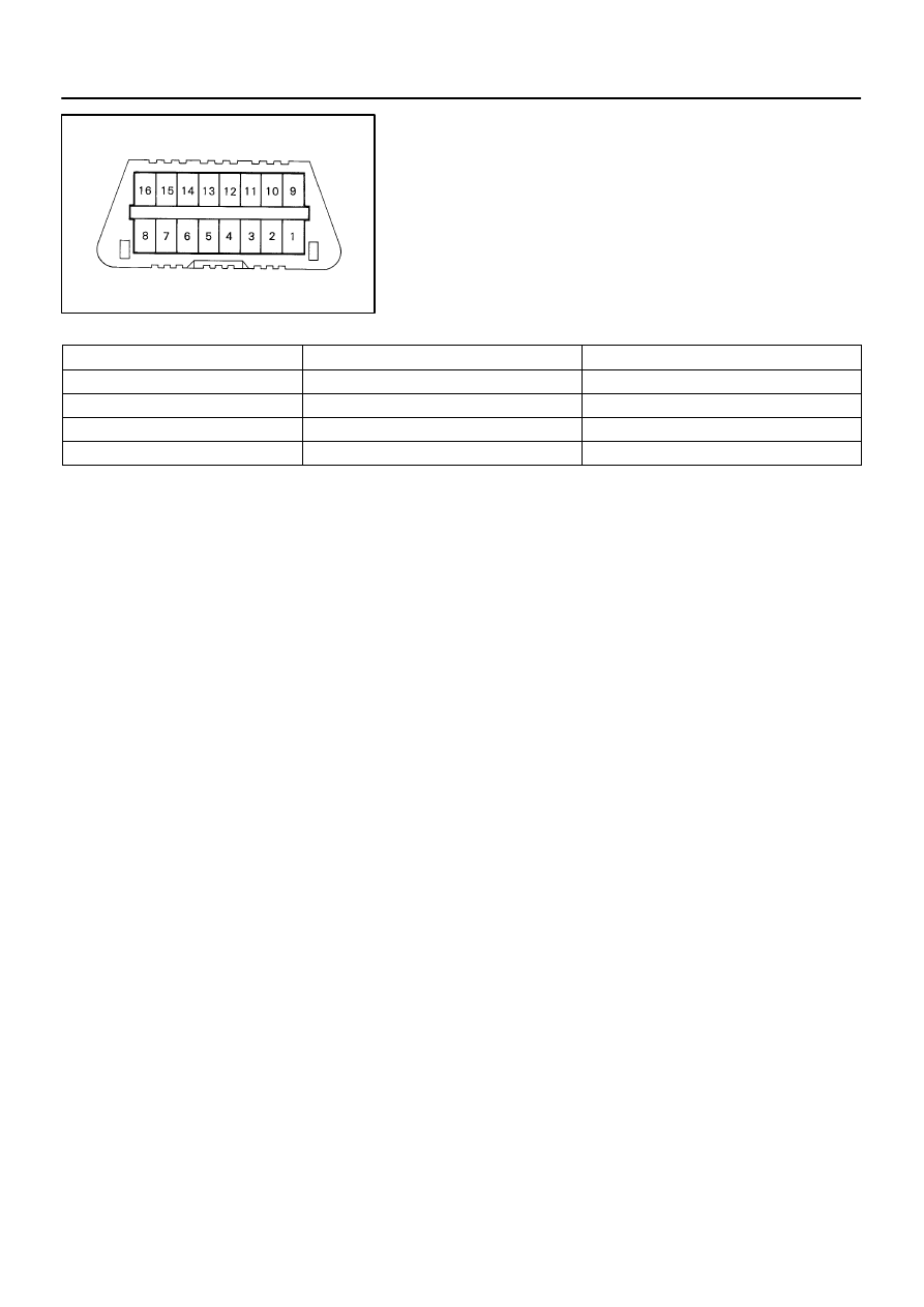
C00083
DLC3
–
DIAGNOSTICS
COMBINATION METER SYSTEM
DI–1625
1819
DIAGNOSIS SYSTEM
INSPECT THE DLC3
The vehicle’s combination meter ECU uses ISO 9141–2 for
communication. The terminal arrangement of the DLC3 com-
plies with SAE J1962 and matches the ISO 9141–2 format.
Tester connection
Condition
Specified condition
7 (Bus
Line) – 5 (Signal ground)
During communication
Pulse generation
4 (Chassis Ground) – Body
Always
Below 1
Ω
5 (Signal Ground) – Body
Always
Below 1
Ω
16 (B+) – Body
Always
10 to 14 V
HINT:
If the display shows UNABLE TO CONNECT TO VEHICLE
when you have connected the cable of the hand–held tester to
the DLC3, turned the ignition switch to the ON position and op-
erated the tester, there is a problem either on the vehicle side
or tester side.
If communication is normal when the tool is connected to
another vehicle, inspect the DLC3 on the original vehicle.
If communication is still impossible when the tool is con-
nected to another vehicle, the problem is probably in the
tool itself, so consult the Service Department listed in the
tool’s instruction manual.
DID8X–01
DI–1626
–
DIAGNOSTICS
COMBINATION METER SYSTEM
1820
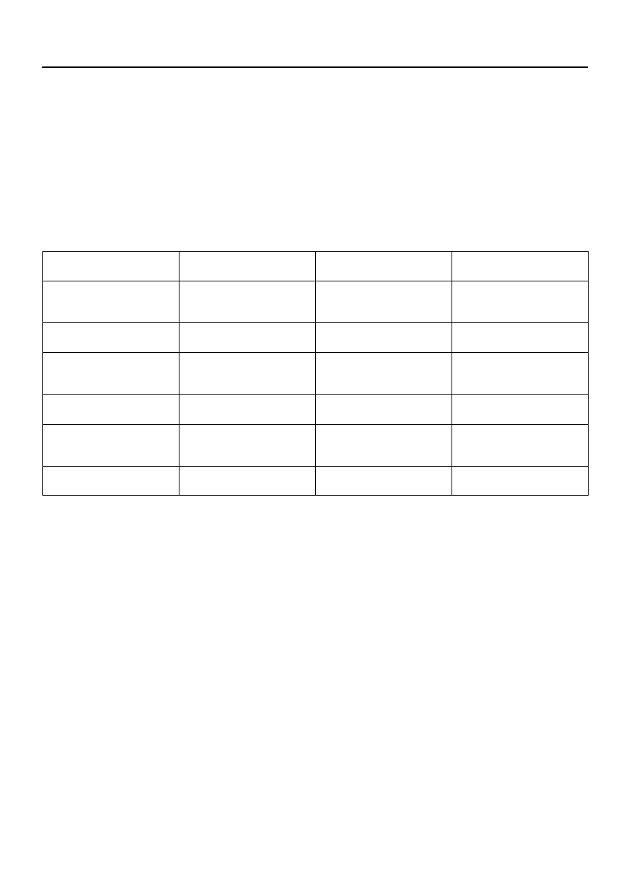
DATA LIST / ACTIVE TEST
DATA LIST
According to the DATA LIST displayed by the hand–held tester, you can read the values of the switches,
sensors, actuators and so on without part removal. Reading the DATA LIST as the first step of troubleshoot-
ing is one method to shorten labor time.
(a)
Warm up the engine.
(b)
Turn the ignition switch off.
(c)
Connect the hand–held tester to the DLC3.
(d)
Turn the ignition switch to the ON position.
(e)
Operate the hand–held tester according to the steps on the display and select ”DATA LIST”.
METER:
Item
Measurement Item /
Range (Display)
Normal Condition
Diagnostic Note
SPEED METER
Vehicle Speed Meter /
Min.: 0 km/h (0 mph)
Max.: 255 km/h (158 mph)
Almost the same as actual vehicle
speed (When driving)
TACHO METER
Engine RPM /
Min.: 0 rpm Max.: 12,750 rpm
Almost the same as actual engine
speed (When engine is running)
FUEL GAUGE
Fuel Input /
Min.: 0 Max.: 255
Tester indication changes accord-
ing to the fuel receiver gauge
angle.
LIGHT RHEOSTAT
Light Control Rheostat /
Min.: 0 Max.: 255
Light control rheostat switch is
Dark (0)
→
Bright (255)
OIL GAUGE
Oil Gauge /
Min.: 0 Max.: 255
Tester indication changes accord-
ing to the oil pressure receiver
gauge angle.
ODO/TRIP SW
ODO / TRIP
ODO/TRIP switch / ON/OFF
ON: Switch is pushed
OFF: Switch is released
Нет комментариевНе стесняйтесь поделиться с нами вашим ценным мнением.
Текст