Toyota Sequoia (2005). Manual — part 528
DI3IS–11
I27730
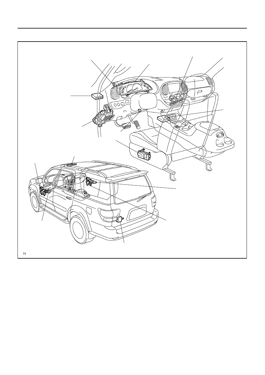
Instrument Panel J/B
Passenger Door ECU
(Power Window Switch)
Combination Meter
Sliding Roof ECU
DLC3
Body ECU
(Located behind
the instrument panel)
Driver Door ECU
(Power Window
Master Switch)
Back Door ECU
(Located inside the back door trim board)
Automatic Light Control Sensor
Memory Seat ECU
& Switch
Airbag
Sensor
Assy
Power Window
Motor Front RH
Limit Switch
Pulse Switch
Power Window
Motor Front LH
Limit Switch
Pulse Switch
A/C ECU
(Integration Control and Panel)
–
DIAGNOSTICS
MULTIPLEX COMMUNICATION SYSTEM
DI–1907
2101
PARTS LOCATION
DIDFB–01
DI–1908
–
DIAGNOSTICS
MULTIPLEX COMMUNICATION SYSTEM
2102
CIRCUIT INSPECTION
DTC
B1211
Driver door ECU communication stop
CIRCUIT DESCRIPTION
This DTC is indicated when communication fails between the driver door ECU and body ECU.
DTC No.
DTC Detecting Condition
Trouble Area
B1211
No communication from driver door ECU for more than 10
Driver door ECU
Wi
h
B1211
No communication from driver door ECU for more than 10
seconds.
Wire harness
Body ECU
I28467
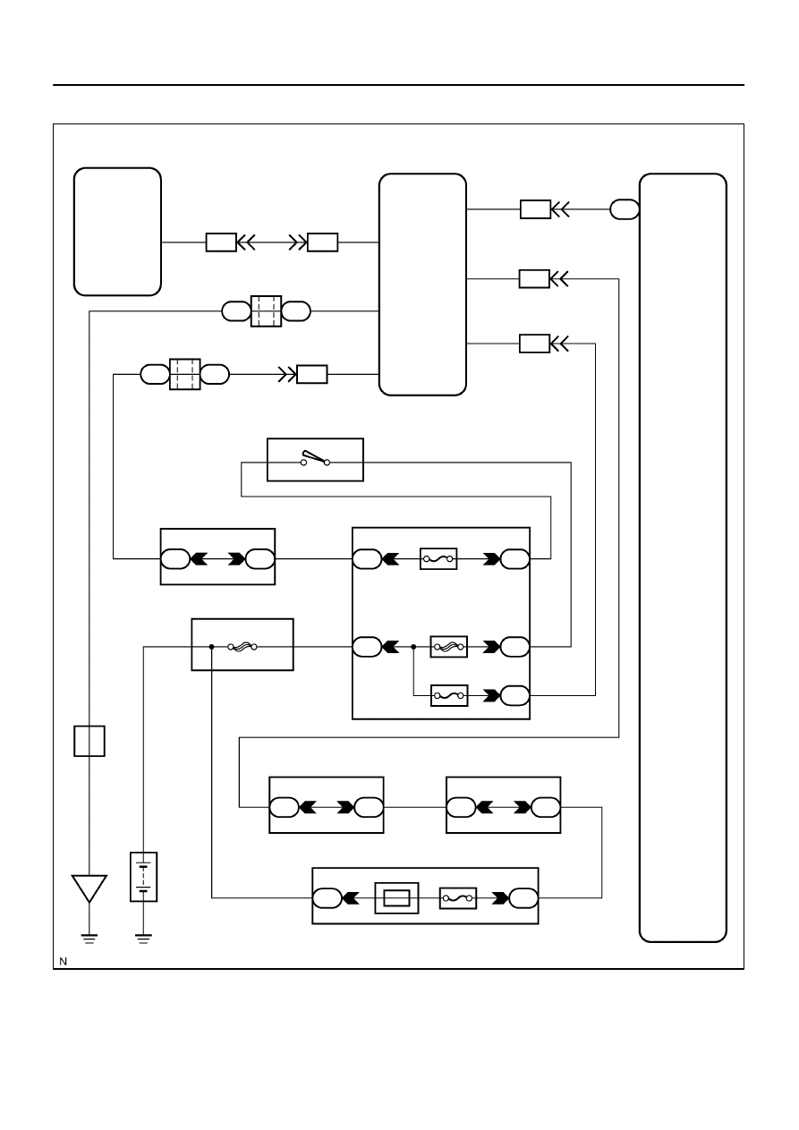
F18
Front Passenger Door ECU
D22
Driver Door ECU
Body ECU
J/C
I18
Ignition Switch
Instrument Panel J/B
Sub J/B No. 3
F10
FL Block
Sub J/B No. 3
Instrument Panel J/B
Engine Room R/B
J8
J/C
Battery
IE
ECU–B
Short Pin
ECU–IG
AM1
PWR No. 1
J/C
B7
IB1
II2
J6
J7
J37
J38
IB1
IB1
IB1
3C
3A
1F
1C
1L
1E
1J
2D
2C
1C
1F
3C
3A
ALT
IG1
AM1
IB1
MPX1
MPX2
GND
SIG
CPUB
BDR
MPX2
MPX1
W–L
W–R
L–W
G–B
W–B
B–R
W–L
G–B
G–B
W–B
B–R
W–R
W–L
B–Y
B–R
B–R
W–L
L–W
W–R
W
W–R
W–R
B
B
D
A
F
A
A
4
8
9
11
22
23
25
1
3
13
20
13
8
2
1
8
8
4
4
1
1
6
1
2
4
8
5
1
1
2
3
1
8
21
–
DIAGNOSTICS
MULTIPLEX COMMUNICATION SYSTEM
DI–1909
2103
WIRING DIAGRAM
DI–1910
–
DIAGNOSTICS
MULTIPLEX COMMUNICATION SYSTEM
2104
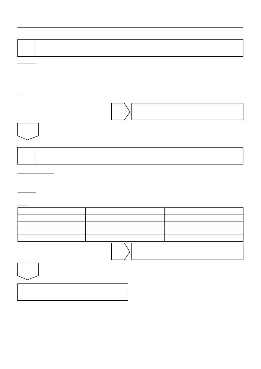
INSPECTION PROCEDURE
1
Check driver door ECU.
CHECK:
Check if the driver door window glass auto up function operates normally through the power window master
switch.
HINT:
With this inspection, the driver door ECU CPU can be diagnosed if it works normally or not.
OK:
Driver door side power window auto up function operates normally.
NG
Go to power source circuit (See page
OK
2
Check wire harness and connector (Driver door ECU – body ECU and driver door
ECU – passenger door ECU).
PREPARATION:
Disconnect connector ”B7” of the body ECU, ”D22” of the driver door ECU and ”F18” the passenger door
ECU.
CHECK:
Measure the resistance according to the values in the table below.
OK:
Symbols (Tester connection)
Condition
Specified condition
MPX1 (B7–22) – MPX2 (D22–8)
Always
Below 1
Ω
MPX1 (D22–20) – MPX2 (F18–11)
Always
Below 1
Ω
MPX1 (B7–22) – Body ground
Always
10 k
Ω
or higher
MPX1 (D22–20) – Body ground
Always
10 k
Ω
or higher
NG
Repair or replace wire harness.
OK
Replace the driver door ECU.
If the problem reoccurs even after replacement, replace the body ECU.
Нет комментариевНе стесняйтесь поделиться с нами вашим ценным мнением.
Текст