Toyota Sequoia (2005). Manual — part 529

–
DIAGNOSTICS
MULTIPLEX COMMUNICATION SYSTEM
DI–1911
2105
DTC
B1212
Front passenger door ECU commu-
nication stop
CIRCUIT DESCRIPTION
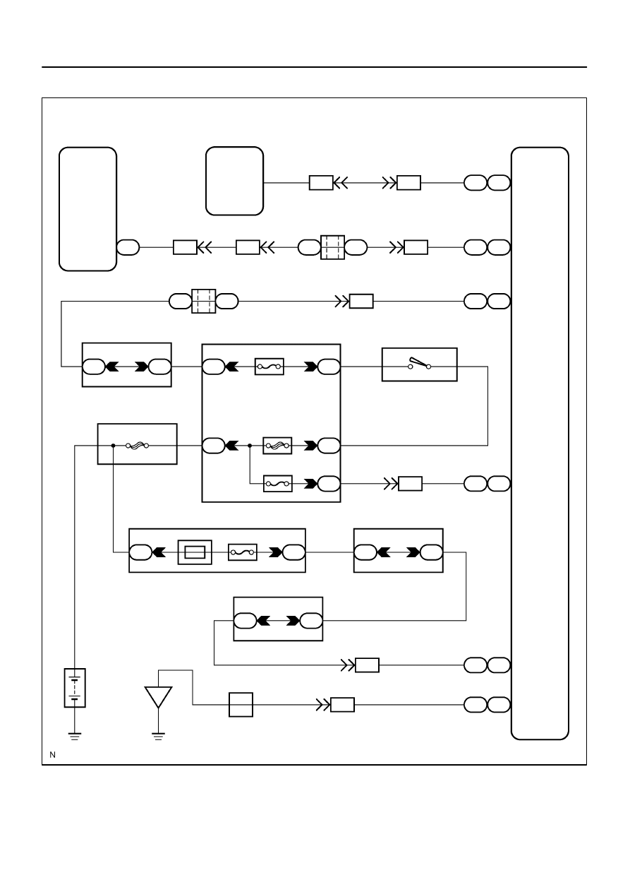
This DTC is indicated when communication fails between the passenger door ECU and body ECU.
DTC No.
DTC Detecting Condition
Trouble Area
B1212
No communication from passenger door ECU for more than 10
Passenger door ECU
Wi
h
B1212
No communication from assenger door ECU for more than 10
seconds.
Wire harness
Body ECU
DIDFC–01
I28468
MPX2
MPX1
D22
Driver Door ECU
Back Door ECU
IB1
F18
Passenger
Door ECU
J/C
II2
BF1
BD2
B11
J37
J38
J/C
J34
J33
II2
II2
MPX2
MPX1
SIG
BDR
GND
F18 F18
F18 F18
F18 F18
F18 F18
F18 F18
F18 F18
G–B
B
B–R
G–B
G–B
B
B
B
B
B–R
B–R
B–R
B–Y
W–L
L–Y
L–Y
B
W–R
W–R
W–R
W–R
W–B
A
J12
J/C
Battery
IF
II2
II2
Sub J/B No. 3
3D
3A
1
1
6
11
13
8
(*1)
(*2)
23
12
(*1)
(*2)
25
20
(*1)
(*2)
21
19
(*1)
(*2)
20
10
(*1)
(*2)
8
11
(*1)
(*2)
Engine Room J/B
ECU–B
Short Pin
2D
2C
1
8
Instrument Panel J/B
1E
1J
2
3
II2
F10
Fusible Link Block
ALT
4
8
5
Instrument Panel J/B
ECU–IG
AM1
PWR No. 2
1F
1C
1L
1C
1F
4
4
1
17
6
1
2
Sub J/B No. 3
3C
3A
8
8
I18
Ignition SW
IG1
AM1
4
8
8
2
1
14
A
G
2
7
(*1): w/ Driving Position Memory
(*2): w/o Driving Position Memory
20
A
A
3
B
1
W–B
CPUB
W
DI–1912
–
DIAGNOSTICS
MULTIPLEX COMMUNICATION SYSTEM
2106
WIRING DIAGRAM
–
DIAGNOSTICS
MULTIPLEX COMMUNICATION SYSTEM
DI–1913
2107
INSPECTION PROCEDURE
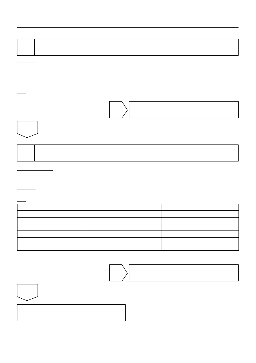
1
Check passenger door ECU.
CHECK:
Check if the passenger door window glass auto up function operates normally through the front passenger
door window switch.
HINT:
With this inspection, the passenger door ECU CPU can be diagnosed if it works normally or not.
OK:
Front passenger side power window auto up function operates normally.
NG
Go to power source circuit (See page
OK
2
Check wire harness and connector (Passenger door ECU – driver door ECU,
back door ECU).
PREPARATION:
Disconnect connector ”D22” of the driver door ECU, ”F18” of the passenger door ECU and ”B11” of the back
door ECU.
CHECK:
Measure the resistance according to the values in the table below.
OK:
Symbols (Tester connection)
Condition
Specified condition
MPX1 (D22–20) – MPX2 (F18–8) (*1)
Always
Below 1
Ω
MPX1 (D22–20) – MPX2 (F18–11) (*2)
Always
Below 1
Ω
MPX2 (B11–1) – MPX1 (F18–20) (*1)
Always
Below 1
Ω
MPX2 (B11–1) – MPX1 (F18–10) (*2)
Always
Below 1
Ω
MPX1 (D22–20) – Body ground
Always
10 k
Ω
or higher
MPX1 (B11–1) – Body ground
Always
10 k
Ω
or higher
*1: w/ Driving Position Memory
*2: w/o Driving Position Memory
NG
Repair or replace wire harness.
OK
Replace the passenger door ECU.
If the problem reoccurs even after replacement, replace the body ECU.

DI–1914
–
DIAGNOSTICS
MULTIPLEX COMMUNICATION SYSTEM
2108
DTC
B1214
Communication bus malfunction
(Short to B+)
DTC
B1215
Communication bus malfunction
(Short to ground)
CIRCUIT DESCRIPTION
DTC B1214 or B1215 is detected when a short to +B or short to ground occurs on the multiplex communica-
tion bus (BEAN). Detecting this condition will disable the multiplex communication bus (BEAN) and output
the corresponding DTC.
DTC NO.
DTC detecting condition
Trouble area
B1214
Short to B+ in multiplex communication system communica-
tion circuit
Driver door ECU
Passenger door ECU
Back door ECU
A/C ECU (Integration control panel)
Combination meter
Memory seat ECU & switch
Wire harness
Body ECU
B1215
Short to ground in multiplex communication system commu-
nication circuit
Driver door ECU
Passenger door ECU
Back door ECU
A/C ECU (Integration control panel)
Combination meter
Memory seat ECU & switch
Wire harness
Body ECU
DI94Y–07
Нет комментариевНе стесняйтесь поделиться с нами вашим ценным мнением.
Текст