Toyota Sequoia (2005). Manual — part 87

–
DIAGNOSTICS
ENGINE
DI–151
345
MONITOR STRATEGY
P0136
Heated rear oxygen sensor (Bank 1) output volt-
age (Output voltage)
P0136
Heated rear oxygen sensor (Bank 1) impedance
(Low)
P0137
Heated rear oxygen sensor (Bank 1) output volt-
age (Low voltage)
P0137
Heated rear oxygen sensor (Bank 1) impedance
(High)
P0138
Heated rear oxygen sensor (Bank 1) output volt-
age (High voltage)
R l t d DTC
P0138
Heated rear oxygen sensor (Bank 1) output volt-
age (Extremely high)
Related DTCs
P0156
Heated rear oxygen sensor (Bank 2) output volt-
age (Output voltage)
P0156
Heated rear oxygen sensor (Bank 2) impedance
(Low)
P0157
Heated rear oxygen sensor (Bank 2) output volt-
age (Low voltage)
P0157
Heated rear oxygen sensor (Bank 2) impedance
(High)
P0158
Heated rear oxygen sensor (Bank 2) output volt-
age (High voltage)
P0158
Heated rear oxygen sensor (Bank 2) output volt-
age (Extremely high)
R
i d
/
t
Main sensors/components
Heated rear oxygen sensor
Required sensors/components
Related sensors/components
Mass air flow meter
Frequency of operation
Once per driving cycle: Active air–fuel ratio control detection
Continuous: Others
Duration
20 sec.: Heated oxygen sensor output (Output voltage, High voltage, Low voltage)
30 sec.: Heated oxygen sensor impedance (Low)
90 sec.: Heated oxygen sensor impedance (High)
10 sec.: Heated oxygen sensor impedance (Extremely high)
MIL operation
2 driving cycles Heated oxygen sensor output (Output voltage, High voltage, Low voltage)
Immediate: Heated oxygen sensor impedance (Low, High, Extremely high)
Sequence of operation
None
TYPICAL ENABLING CONDITIONS
It
Specification
Item
Minimum
Maximum
The monitor will run whenever these
DTCs are not present
See page
Heated oxygen sensor output voltage (Output voltage, High voltage and Low voltage):
Active air–fuel ratio control
Executing
Active air–fuel ratio control being when all
of following conditions met
–
Battery voltage
11 V
–
Engine coolant temperature
75
°
C (167
°
F)
–
Idle
OFF
Engine RPM
–
3,200 rpm

DI–152
–
DIAGNOSTICS
ENGINE
346
A/F sensor status
Activated
Fuel–cut
OFF
Engine load
10 to 70%
Shift position
4th
–
Heated oxygen sensor impedance (Low):
Battery voltage
11 V
–
Estimated sensor temperature
–
700
°
C (1,292
°
F)
ECM monitor
Completed
P0606
Not set
Heated oxygen sensor impedance (High):
Battery voltage
11 V
–
Estimated sensor temperature
450
°
C (842
°
F)
–
ECM monitor
Completed
P0606
Not set
Heated oxygen sensor output voltage (Extremely high):
Battery voltage
11 V
–
Time after engine start
2 sec.
–
TYPICAL MALFUNCTION THRESHOLDS
Detection Criteria
Threshold
Heated oxygen sensor output voltage (Output voltage):
Either of the following conditions is met:
Condition 1 or 2
1. All of the following conditions are met:
Condition (a), (b) and (c)
(a) Commanded air–fuel ratio
14.3 or less
(b) Rear HO2S voltage
0.21 to 0.59 V
(c) OSC (Oxygen Storage Capacity of catalyst)
3 g or more
2. All of the following conditions are met:
Condition (a), (b) and (c)
(a) Commanded air–fuel ratio
14.9 or more
(b) Rear HO2S voltage
0.21 to 0.59 V
(c) OSC (Oxygen Storage Capacity of catalyst)
3 g or more
Heated oxygen sensor output voltage (Low voltage):
All of the following conditions are met:
Condition 1, 2 and 3
1. Commanded air–fuel ratio
14.3 or less
2. Rear HO2S voltage
Less than 0.21 V
3. OSC (Oxygen Storage Capacity of catalyst)
3 g or more
Heated oxygen sensor output voltage (High voltage):
All of the following conditions are met:
Condition 1, 2 and 3
1. Commanded air–fuel ratio
14.9 or more
2. Rear HO2S voltage
More than 0.59 V
3. OSC (Oxygen Storage Capacity of catalyst)
3 g or more
Heated oxygen sensor impedance (Low):
Duration of following condition
30 sec. or more
Heated oxygen sensor impedance
Less than 5
Ω
Heated oxygen sensor impedance (High):
Duration of following condition
90 sec. or more

–
DIAGNOSTICS
ENGINE
DI–153
347
Heated oxygen sensor impedance
348.1 M
Ω
or more
Heated oxygen sensor output voltage (Extremely high):
Duration of following condition
10 sec. or more
Heated oxygen sensor voltage
More than 1.2 V
COMPONENT OPERATING RANGE
Parameter
Standard Value
Heated oxygen sensor voltage
Varies between 0.1 to 0.9 V
MONITOR RESULT
Refer to page
for detailed information.
The test value and test limit information are described as shown in the following table. Check the monitor
result and test values after performing the monitor drive pattern (refer to ”Confirmation Monitor”).
MID (Monitor Identification Data) is assigned to each emissions–related component.
TID (Test Identification Data) is assigned to each test value.
HO2S bank 1 sensor 2
MID
TID
Scaling
Description of Test Value
Minimum Test Limit
Maximum Test Limit
$02
$07
Multiply by 0.001
(V)
Minimum sensor voltage
Minimum test limit
Maximum test limit
$02
$08
Multiply by 0.001
(V)
Maximum sensor voltage
Minimum test limit
Maximum test limit
$02
$8F
Multiply by 0.001
(g)
Maximum oxygen storage capacity
0
Maximum test limit
HO2S bank 2 sensor 2
MID
TID
Scaling
Description of Test Value
Minimum Test Limit
Maximum Test Limit
$06
$07
Multiply by 0.001
(V)
Minimum sensor voltage
Minimum test limit
Maximum test limit
$06
$08
Multiply by 0.001
(V)
Maximum sensor voltage
Minimum test limit
Maximum test limit
$06
$8F
Multiply by 0.001
(g)
Maximum oxygen storage capacity
0
Maximum test limit
WIRING DIAGRAM
Refer to DTC P2195 on page
.
A23661
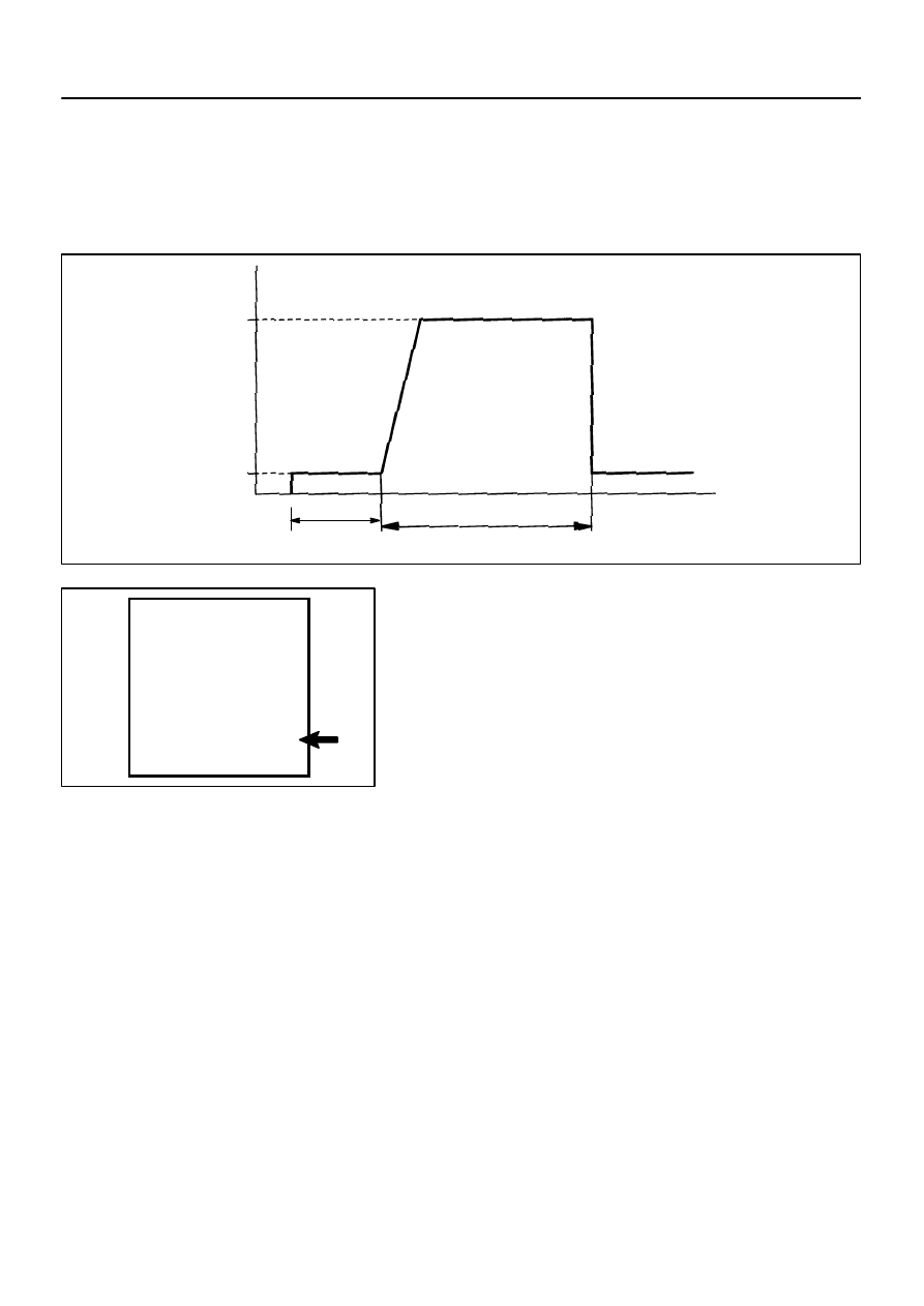
Vehicle Speed
(64 km/h and 113 km/h)
Between
40 mph and 70 mph
Idling
Ignition Switch OFF
10 minutes
Time
Warm up
(Note: Even if vehicle stops during driving pattern, test can be resumed)
NOTICE:
This test will not be completed
if the vehicle is driven under
absolutely constant speed
conditions such as with cruise
control activated.
(h)
(g)
MISFIRE MON . . . . . . AVAIL
READINESS TESTS
CAT EVAL . . . . . . . INCMPL
HTD CAT EVAL . . . . . .. N/A
EVAP EVAL . . . . . ... INCMPL
2nd AIR EVAL . . . . . . .. N/A
A/C EVAL . . . . . . . . N/A
O2S EVAL . . . . . . INCMPL
O2S HTR EVAL . . . . .. INCMPL
EGR EVAL . . . . . . . ...N/A
COMP MON . . . . . . AVAIL
FUEL SYS MON . . . . ... AVAIL
A76855
A23660
DI–154
–
DIAGNOSTICS
ENGINE
348
CONFIRMATION DRIVING PATTER
HINT:
This confirmation driving pattern is used in steps 5, 8 and 11 of the following diagnostic troubleshooting
procedure when using either a hand–held tester.
Performing this confirmation pattern will activate the Heated Oxygen (HO2) sensor monitor. (The cata-
lyst monitor is performed simultaneously.) This is very useful for verifying the completion of a repair.
(a)
Connect a hand–held tester to the DLC3.
(b)
Turn the ignition switch to ON.
(c)
Turn the tester or scan tool ON.
(d)
Clear DTCs (where set) (see page
(e)
If using a hand–held tester, select the following menu
items: DIAGNOSIS / CARB OBD II / READINESS
TESTS.
(f)
Check that O2S EVAL is INCMPL (incomplete).
(g)
Start the engine and warm it up.
(h)
Drive the vehicle at between 40 mph and 70 mph (64 km/h
and 113 km/h) for at least 10 minutes.
(i)
Note the state of the Readiness Tests items. Those items
will change to COMPL (complete) as O2S EVAL monitor
operates.
(j)
On the tester, select the following menu items: DIAGNO-
SIS / ENHANCED OBD II / DTC INFO / PENDING
CODES and check if any DTCs (any pending DTCs) are
set.
HINT:
If O2S EVAL does not change to COMPL, and any pending
DTCs fail to set, extend the driving time.
Нет комментариевНе стесняйтесь поделиться с нами вашим ценным мнением.
Текст