Toyota Sequoia (2005). Manual — part 86
B17386
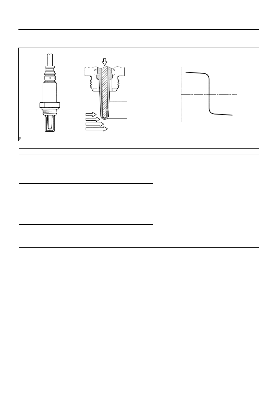
Housing
Solid Electrolyte
(Zirconia Element)
Platinum Electrode
Heater
Coating (Ceramic)
Exhaust Gas
Cover
Ideal Air–Fuel Mixture
Output V
oltage
Richer – Air Fuel Ratio – Leaner
Atmospheric Air
–
DIAGNOSTICS
ENGINE
DI–147
341
ing improperly due to internal malfunctions, the ECM is unable to compensate for deviations in the primary
air–fuel ratio control.
DTC No.
DTC Detecting Condition
Trouble Area
P0136
P0156
During active air–fuel ratio control, following conditions (a) and
(b) met for certain period of time (2 trip detection logic):
(a) Heated Oxygen (HO2) sensor voltage does not decrease to
less than 0.2 V
(b) HO2 sensor voltage does not increase to more than 0.6 V
Open or short in HO2 sensor (sensor 2) circuit
HO2 sensor (sensor 2)
HO2 sensor heater (sensor 2)
Air–Fuel Ratio (A/F) sensor (sensor 1)
P0136
P0156
Sensor impedance less than 5
Ω
for more than 30 seconds
when ECM presumes sensor to being warmed up and operat-
ing normally (1 trip detection logic)
Air Fuel Ratio (A/F) sensor (sensor 1)
EFI relay
Gas leakage from exhaust system
P0137
P0157
During active air–fuel ratio control, following conditions (a) and
(b) met for certain period of time (2 trip detection logic):
(a) HO2 sensor voltage output less than 0.21 V
(b) Target air–fuel ratio rich
Open in HO2 sensor (sensor 2) circuit
HO2 sensor (sensor 2)
HO2 sensor heater (sensor 2)
P0137
P0157
High impedance:
Sensor impedance 348.1 M
Ω
or more for more than 90 se-
conds when ECM presumes sensor to being warmed up and
operating normally (1 trip detection logic)
HO2 sensor heater (sensor 2)
EFI relay
Gas leakage from exhaust system
P0138
P0158
During active air–fuel ratio control, following conditions (a) and
(b) met for certain period of time (2 trip detection logic):
(a) HO2 sensor voltage output 0.59 V or more
(b) Target air–fuel ratio lean
Short in HO2 sensor (sensor 2) circuit
HO2 sensor (sensor 2)
ECM internal circuit malfunction
P0138
P0158
HO2 sensor voltage output exceeds 1.2 V for more than 30
seconds (1 trip detection logic)
ECM internal circuit malfunction
B17387
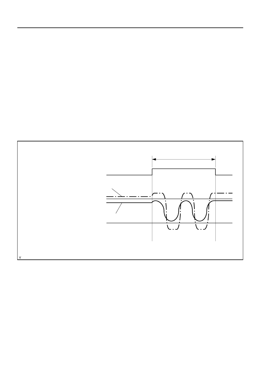
Active air–fuel
ratio control
Off
Operation
15 to 20 seconds
HO2 sensor
voltage
Abnormal
Normal
0.21 V
0.59 V
HO2 SENSOR CIRCUIT MALFUNCTION (P0136, P0156: ABNORMAL VOLTAGE)
DI–148
–
DIAGNOSTICS
ENGINE
342
MONITOR DESCRIPTION
Active Air–Fuel Ratio Control
The ECM usually performs air–fuel ratio feedback control so that the Air–Fuel Ratio (A/F) sensor output indi-
cates a near stoichiometric air–fuel level. This vehicle includes active air–fuel ratio control in addition to regu-
lar air–fuel ratio control. The ECM performs active air–fuel ratio control to detect any deterioration in the
Three–Way Catalytic Converter (TWC) and Heated Oxygen (HO2) sensor malfunctions (refer to the diagram
below).
Active air–fuel ratio control is performed for approximately 15 to 20 seconds while driving with a warm engine.
During active air–fuel ratio control, the air–fuel ratio is forcibly regulated to become lean or rich by the ECM.
If the ECM detects a malfunction, one of the following DTCs is set: DTC P0136, P0156 (abnormal voltage
output), P0137, P0157 (open circuit) and P0138, P0158 (short circuit).
Abnormal Voltage Output of HO2 Sensor (DTC P0136, P0156)
While the ECM is performing active air–fuel ratio control, the air–fuel ratio is forcibly regulated to become
rich or lean. If the sensor is not functioning properly, the voltage output variation is small. For example, when
the HO2 sensor voltage does not decrease to less than 0.21 V and does not increase to more than 0.59 V
during active air–fuel ratio control, the ECM determines that the sensor voltage output is abnormal and sets
DTC P0136.
B17388
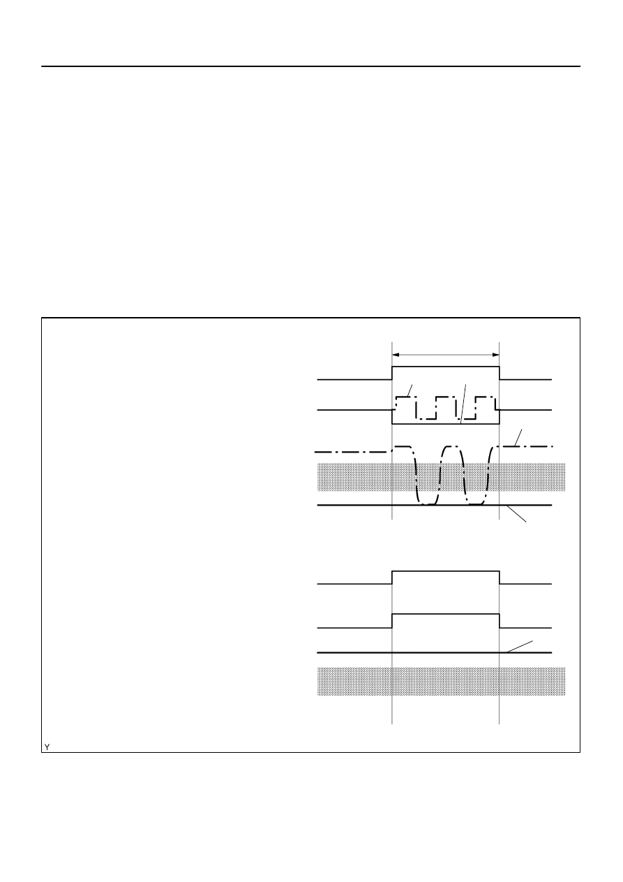
Active air–fuel
ratio control
Target air–fuel ratio
HO2 sensor
voltage
Stoichiometric
Air–Fuel Level
Rich
0.21 V
Active air–fuel
ratio control
Target air–fuel ratio
HO2 sensor
voltage
Lean
HO2 SENSOR CIRCUIT LOW VOLTAGE (P0137, P0157: OPEN)
HO2 SENSOR CIRCUIT HIGH VOLTAGE (P0138, P0158: SHORT)
Off
Operation
Off
Normal
Abnormal
15 to 20 seconds
0.59 V
Abnormal
Abnormal
Normal
Operation
Stoichiometric
Air–Fuel Level
–
DIAGNOSTICS
ENGINE
DI–149
343
Open or Short in the Heated Oxygen (HO2) Sensor Circuit (DTC P0137, P0157, P0138 or P0158)
During active air–fuel ratio control, the ECM calculates the Oxygen Storage Capacity (OSC)* of the Three–
Way Catalytic Converter (TWC) by forcibly regulating the air–fuel ratio to become rich or lean.
If the HO2 sensor has an open or short, or the voltage output of the sensor noticeably decreases, the OSC
indicates an extraordinarily high value. Even if the ECM attempts to continue regulating the air–fuel ratio to
become rich or lean, the HO2 sensor output does not change.
While performing active air–fuel ratio control, when the target air–fuel ratio is rich and the HO2 sensor voltage
output is 0.21 V or less (lean), the ECM interprets this as an abnormally low sensor output voltage and sets
DTC P0137 or P0157. When the target air–fuel ratio is lean and the voltage output is 0.59 V or more (rich)
during active air–fuel ratio control, the ECM determines that the sensor voltage output is abnormally high,
and sets DTC P0138 or P0158.
HINT:
DTC P0138 or P0158 is also set if the HO2 sensor voltage output is more than 1.2 V for 30 seconds or more.
*: The TWC has the capability to store oxygen. The OSC and the emission purification capacity of the TWC
are mutually related. The ECM determines whether the catalyst has deteriorated, based on the calculated
OSC value (see page

B17389
Temperature
C (
F)
Impedance
Ω
300
400
500
600
700
800
(572)
5
10
100
1,000
15,000
(752)
(932)
(1,112)
(1,292)
(1,472)
DTC Detection Area
Interrelation between temperature of
the element and impedance:
DI–150
–
DIAGNOSTICS
ENGINE
344
High or Low Impedance of Heated Oxygen (HO2) Sensor (DTC P0136, P0156, P0137 or P0157)
During normal air–fuel ratio feedback control, there are small
variations in the exhaust gas oxygen concentration.
In order to
continuously monitor the slight variation of the HO2 sensor sig-
nal while the engine is running, the impedance* of the sensor
is measured by the ECM. The ECM determines that there is a
malfunction in the sensor when the measured impedance devi-
ates from the standard range.
*: The effective resistance in an alternating current electrical cir-
cuit.
HINT:
The impedance can not be measured using an ohmme-
ter.
DTC P0136 or P0156 indicates the deterioration of the
HO2 sensor. The ECM sets the DTC by calculating the im-
pedance of the sensor when the typical enabling condi-
tions are satisfied (1 driving cycle).
DTC P0137 or P0157 indicates an open circuit in the HO2
sensor (1 driving cycle). The ECM sets this DTC when the
impedance of the sensor exceeds the threshold 348.1
M
Ω
.
Нет комментариевНе стесняйтесь поделиться с нами вашим ценным мнением.
Текст