Toyota Sequoia (2005). Manual — part 73

–
DIAGNOSTICS
ENGINE
DI–95
289
DTC No.
DTC Detecting Condition
Trouble Area
P0037
Heater current is 0.25 A or less when the heater operates with
Open in heater circuit of heated oxygen sensor
Heated oxygen sensor heater
P0037
P0057
Heater current is 0.25 A or less when the heater o erates with
more than 10.5 V positive battery voltage
Heated oxygen sensor heater
EFI relay
ECM
P0038
P0058
When heater operates, heater current exceeds 2.0 A
Short in heater circuit of heated oxygen sensor
Heated oxygen sensor heater
EFI relay
ECM
HINT:
Bank 1 refers to bank that includes cylinder No. 1.
Bank 2 refers to bank that does not includes cylinder No. 1.
Sensor 1 refers to the sensor closer to the engine assembly.
Sensor 2 refers to the sensor farther away from the engine assembly.
MONITOR DESCRIPTION
The sensing portion of the heated oxygen sensor has a zirconia element which is used to detect oxygen
concentration in the exhaust. If the zirconia element is at the proper temperature and difference of the oxy-
gen concentration between the inside and outside surface of sensor is large, the zirconia element will gener-
ate voltage signals. In order to increase the oxygen concentration detecting capacity in the zirconia element,
the ECM supplements the heat from the exhaust with heat from a heating element inside the sensor. When
current in the sensor is out of the standard operating range, the ECM interprets this as a fault in the heated
oxygen sensor and sets a DTC.
Example:
The ECM will set a high current DTC if the current in the sensor is more than 2.0 A when the heater is OFF.
Similarly, the ECM will set a low current DTC if the current is less than 0.3 A when the heater is ON.
MONITOR STRATEGY
P0037
Rear HO2S heater (Bank 1) range check (Low
Current)
R l t d DTC
P0038
Rear HO2S heater (Bank 1) range check (High
Current)
Related DTCs
P0057
Rear HO2S heater (Bank 2) range check (Low
Current)
P0058
Rear HO2S heater (Bank 2) range check (High
Current)
R
i d
/
t
Main sensors/components
HO2S heater
Required sensors/components
Related sensors/components
Vehicle speed sensor (VSS)
Frequency of operation
Continuous
Duration
0.3 sec.
MIL operation
Immediate
Sequence of operation
None

DI–96
–
DIAGNOSTICS
ENGINE
290
TYPICAL ENABLING CONDITIONS
It
Specification
Item
Minimum
Maximum
The monitor will run whenever these
DTCs are not present
See page
P0037, P0057 (Low current):
Battery voltage
10.5 V
–
All heater is turned OFF and intrusive
heating is operated when the following
conditions are met
Condition (a) and (b)
(a) Heater
ON
(b) Heater current
–
0.3 A
P0038, P0058 (High current):
Case 1:
Battery voltage
10.5 V
–
Engine
Running
Starter
OFF
Intrusive heating
Not operating
Case 2:
Battery voltage
10.5 V
–
All heater is turned OFF and intrusive
heating is operated when the following
conditions are met
Condition (a) and (b)
(a) Heater
ON
(b) Heater current
2 A
–
TYPICAL MALFUNCTION THRESHOLDS
Detection Criteria
Threshold
P0037, P0057 (Low current):
HO2S heater current during intrusive heating
Less than 0.3 A (when battery voltage is 10.5 V or more)
P0038, P0058 (High current):
Case 1:
HO2S heater current
2 A or more
Case 2:
HO2S heater current during intrusive heating
More than 2 A
COMPONENT OPERATING RANGE
Parameter
Standard Value
HO2S heater current
0.4 to 1 A (at idle, warmed–up engine and +B: 11 to 14 V)

–
DIAGNOSTICS
ENGINE
DI–97
291
MONITOR RESULT
Refer to page
for detailed information.
The test value and test limit information are described as shown in the following table. Check the monitor
result and test values after performing the monitor drive pattern (see page
).
TID (Test Identification Data) is assigned to each emissions–related component.
TLT (Test Limit Type):
If TLT is 0, the component is malfunctioning when the test value is higher than the test limit.
If TLT is 1, the component is malfunctioning when the test value is lower than the test limit.
CID (Component Identification Data) is assigned to each test value.
Unit Conversion is used to calculate the test value indicated on generic tools.
TID $04: HO2S heater
TLT
CID
Unit Conversion
Description of Test Data
Description of Test Limit
1
$02
Multiply by 0.000076
(A)
Maximum HO2S heater current
(Bank 1 Sensor 2)
Malfunction threshold for HO2S heater
1
$20
Multiply by 0.000076
(A)
Maximum HO2S heater current
(Bank 2 Sensor 2)
Malfunction threshold for HO2S heater
A23550
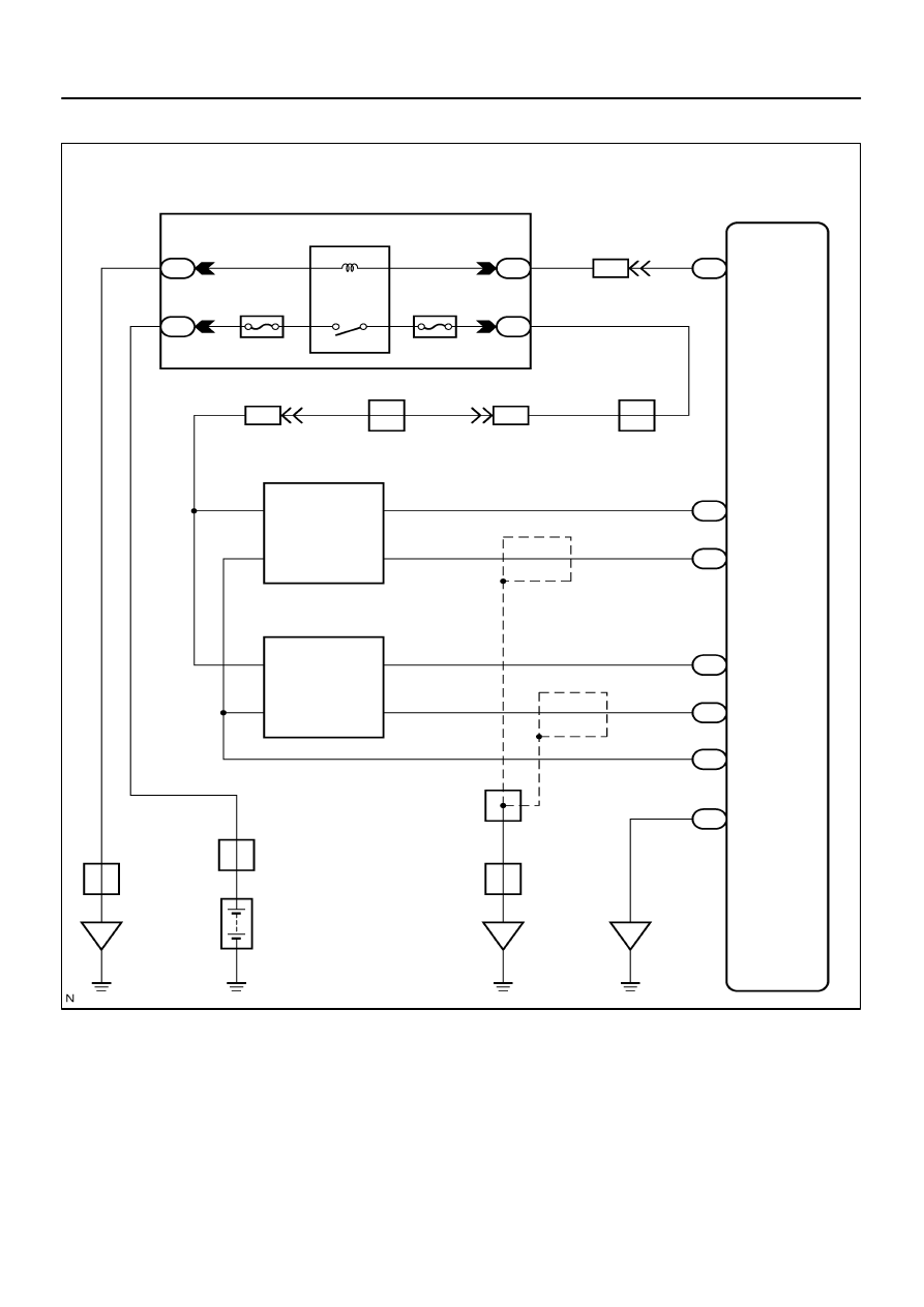
Battery
2F
ECM
OX1B
HT2B
OX2B
33
Y
A
G–R
3
2
E
R
B–W
ED
W–B
5
4
5
1
22
J2
IG4
HTR2
NTL2
OXR2
E8
F10
Fusible Link
Block
G–R
EC
2D
1
1
2H
6
2A
2
EFI Relay
EFI No. 1
EFI No. 2
J/C
IA4
G–R
HT1B
8
5
18
E8
E7
E7
E4
G–R
G–R
14
IA4
B–W
OXL2
1
4
A
G–R
Engine Room J/B
J42
J/C
A
B
J5
J/C
W–R
E8
E6
G–W
BR
BR
H4 Heated Oxygen Sensor
(Bank 2 Sensor 2)
H2 Heated Oxygen Sensor
(Bank 1 Sensor 2)
J16
28
1
(Shielded)
B
E
B
EB
J42
J/C
G–W
G–W
E1
B
G
J/C
E1
+B
+B
E1
E2
MREL
(Shielded)
C
C
C
BR
DI–98
–
DIAGNOSTICS
ENGINE
292
WIRING DIAGRAM
Нет комментариевНе стесняйтесь поделиться с нами вашим ценным мнением.
Текст