Toyota Sequoia (2005). Manual — part 71
A02961
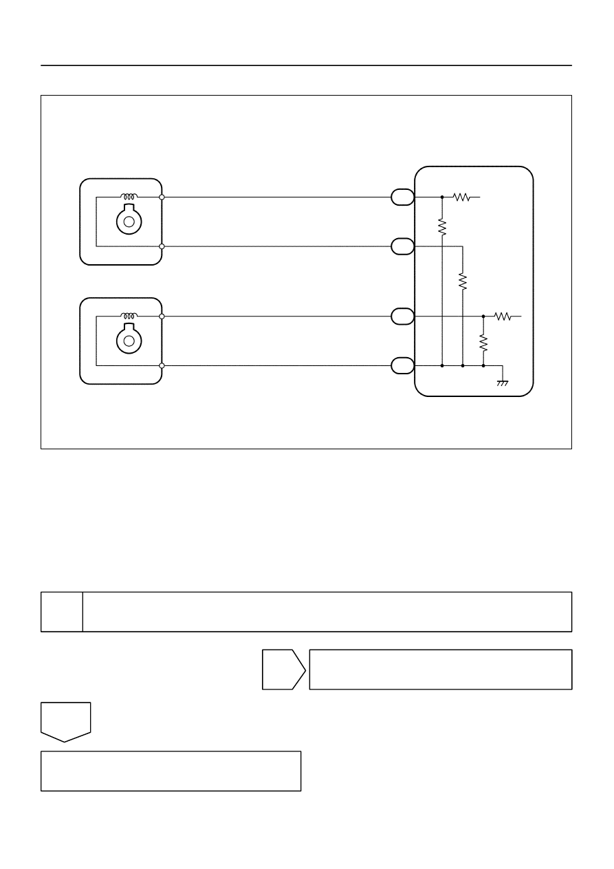
V5
VVT Sensor (Bank 1)
ECM
1
2
R
G
Y
L
VVL+
VVL–
VVR+
E5
18
19
19
18
VVR–
1
2
E5
E4
E4
V6
VVT Sensor (Bank 2)
–
DIAGNOSTICS
ENGINE
DI–87
281
WIRING DIAGRAM
INSPECTION PROCEDURE
HINT:
If DTC P0016 is displayed, check left bank VVT sensor.
If DTC P0018 is displayed, check right bank VVT sensor.
Read freeze frame data using hand–held tester or OBD II scan tool. Because freeze frame records
the engine conditions when the malfunction is detected. When troubleshooting, it is useful for deter-
mining whether the vehicle was running or stopped, the engine was warmed up or not, the air–fuel ratio
was lean or rich, etc. at the time of the malfunction.
1
Check valve timing (Check for loose and jumping teeth of timing belt) (See page
NG
Adjust valve timing (Repair or replace timing
belt).
OK
Replace ECM (See page
A23512
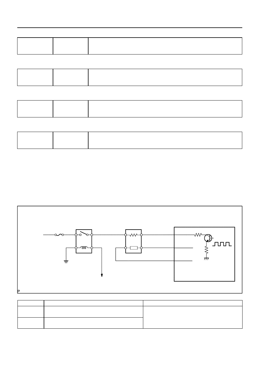
Reference (Bank 1 Sensor 1 System Drawing):
A/F Sensor
A/F Relay
Heater
Sensor
A1A+
HA1A
Duty
Control
ECM
From
Battery
A/F Heater
Fuse
A1A–
To EFI Relay
DI–88
–
DIAGNOSTICS
ENGINE
282
DTC
P0031
Oxygen (A/F) Sensor Heater Control Circuit
Low (Bank 1 Sensor 1)
DTC
P0032
Oxygen (A/F) Sensor Heater Control Circuit
High (Bank 1 Sensor 1)
DTC
P0051
Oxygen (A/F) Sensor Heater Control Circuit
Low (Bank 2 Sensor 1)
DTC
P0052
Oxygen (A/F) Sensor Heater Control Circuit
High (Bank 2 Sensor 1)
HINT:
Although each DTC title (DTC description) says ”oxygen sensor”, these DTCs are related to the ”A/F sensor”.
CIRCUIT DESCRIPTION
Refer to DTC P2195 on page
.
HINT:
The ECM provides a pulse width modulated control circuit to adjust current through the heater. The A/F sen-
sor heater circuit uses a relay on the B+ side of the circuit.
DTC No.
DTC Detection Condition
Trouble Area
P0031
P0051
Heated current is 0.8 A or less when heater operates
(1 trip detection logic)
Open or short in heater circuit of A/F sensor
A/F sensor heater
P0032
P0052
When the heater operates, heated current exceeds 19.7 A
(1 trip detection logic)
A/F sensor heater
A/F sensor heater relay
ECM
DIDFP–01

–
DIAGNOSTICS
ENGINE
DI–89
283
HINT:
Bank 1 refers to the bank that includes cylinder No.1.
Bank 2 refers to the bank that does not include cylinder No.1.
Sensor 1 refers to the sensor closest to the engine assembly.
Sensor 2 refers to the sensor farthest away from the engine assembly.
MONITOR DESCRIPTION
The ECM uses the Air–Fuel Ratio sensor (A/F sensor) information to regulate the air–fuel ratio close to the
stoichiometric ratio. This maximizes the catalytic converter’s ability to purify exhaust gases. The sensor de-
tects oxygen levels in the exhaust gas and sends this signal to the ECM.
The inner surface of the sensor element is exposed to outside air. The outer surface of the sensor element
is exposed to exhaust gas. The sensor element is made of platinum coated zirconia and includes an inte-
grated heating element. The zirconia element generates a small voltage when there is a large difference in
the oxygen concentrations of the exhaust and the outside air. The platinum coating amplifies the voltage
generation. When heated, the sensor becomes very efficient. If the temperature of the exhaust is low, the
sensor will not generate useful voltage signals without supplemental heating. The ECM regulates the sup-
plemental heating using a duty–cycle approach to regulate the average current in the heater element. If the
heater current is out of the normal range, the sensor’s output signals will be inaccurate and the ECM can
not regulate the air–fuel ratio properly.
When the heater current is out of the normal operating range, the ECM interprets this as a malfunction and
sets a DTC.
MONITOR STRATEGY
P0031
A/F sensor heater (Bank 1) range check (Low
current)
R l t d DTC
P0032
A/F sensor heater (Bank 1) range check (High
current)
Related DTCs
P0051
A/F sensor heater (Bank 2) range check (Low
current)
P0052
A/F sensor heater (Bank 2) range check (High
current)
R
i d
/
t
Main sensors/components
A/F sensor heater
Required sensors/components
Related sensors/components
–
Frequency of operation
Continuous
Duration
10 sec.
MIL operation
Immediate
Sequence of operation
None
TYPICAL ENABLING CONDITIONS
It
Specification
Item
Minimum
Maximum
The monitor will run whenever these
DTCs are not present
See page
P0031, P0051 (Low current):
Battery voltage
10.5 V
–
A/F sensor heater duty ratio
50%
–
Time after engine start
10 sec.
–
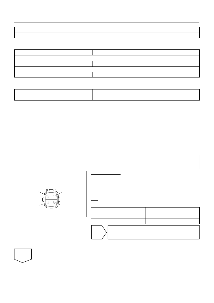
B17396
HT
+B
AF–
AF+
Sensor 1
A/F Sensor
Component Side:
Front View
DI–90
–
DIAGNOSTICS
ENGINE
284
P0032, P0052 (High current):
Time after engine start
10 sec.
–
TYPICAL MALFUNCTION THRESHOLDS
Detection Criteria
Threshold
P0031, P0051 (Low current):
A/F sensor heater current
Less than 0.8 A
P0032, P0052 (High current):
A/F sensor heater current
More than 10 A
COMPONENT OPERATING RANGE
Parameter
Standard Value
A/F sensor heater current
1.8 to 3.4 A at 20
°
C (68
°
F)
WIRING DIAGRAM
Refer to DTC P2195 on page
.
INSPECTION PROCEDURE
HINT:
Read freeze frame data using a hand–held tester or OBD II scan tool. Freeze frame data record the engine
condition when malfunctions are detected. When troubleshooting, freeze frame data can help determine if
the vehicle was moving or stationary, if the engine was warmed up or not, if the air–fuel ratio was lean or
rich, and other data, from the time the malfunction occurred.
1
Check resistance of air–fuel ratio (A/F) sensor heater.
PREPARATION:
Disconnect the air–fuel ratio (A/F) sensor connector.
CHECK:
Measure resistance between the terminals of the A/F sensor
connector.
OK:
Standard:
Tester Connection
Specified Condition
HT (1) – +B (2)
1.8
Ω
to 3.4
Ω
at 20
C (68
F)
HT (1) – AF– (4)
10 k
Ω
or higher
NG
Replace air–fuel ratio (A/F) sensor.
OK
Нет комментариевНе стесняйтесь поделиться с нами вашим ценным мнением.
Текст