Toyota Sequoia (2005). Manual — part 287
–
DIAGNOSTICS
ABS WITH EBD & BA & TRAC & VSC SYSTEM
DI–943
1137
INSPECTION PROCEDURE
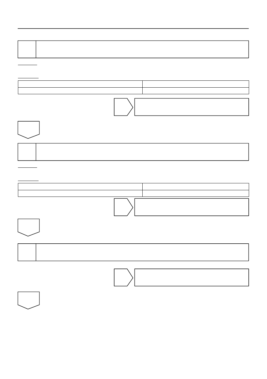
1
Check engine control system.
CHECK:
Check engine control system (See page
).
RESULT:
DTC is not output
A
DTC is output
B
B
Repair engine control system according to the
output code (See page
).
A
2
Check DTC of translate ECU.
CHECK:
Check DTC of the translate ECU (See page
RESULT:
DTC is output (53, 65, 94)
A
DTC is not output
B
B
Go to step 4.
A
3
Check for open and short circuit in harness and connector between skid control
ECU and translate ECU (CAN1 circuit).
NG
Repair or replace harness or connector
(CAN1 circuit).
OK

DI–944
–
DIAGNOSTICS
ABS WITH EBD & BA & TRAC & VSC SYSTEM
1138
4
Replace the translate ECU and check if trouble occurs again.
PREPARATION:
(a)
Clear the DTC (See page
(b)
Turn the ignition switch OFF.
CHECK:
Turn the ignition switch to the ON position, and check if the same DTC still remains in the memory.
RESULT:
DTC is output
A
DTC is not output
B
B
END
A
Replace skid control ECU
(See page
).
NOTICE:
When replacing the skid control ECU, perform zero point calibration (See page
).

–
DIAGNOSTICS
ABS WITH EBD & BA & TRAC & VSC SYSTEM
DI–945
1139
DTC
C1223 / 43
Malfunction in ABS Control System
CIRCUIT DESCRIPTION
HINT:
This DTC is output when the VSC system detects a malfunction in the ABS system.
DTC No.
DTC Detecting Condition
Trouble Area
C1223 / 43
ABS control system is abnormal.
ABS control system
INSPECTION PROCEDURE
1
Check DTC (See page
PREPARATION:
(a)
Clear the DTC.
(b)
Turn the ignition switch OFF.
CHECK:
Turn the ignition switch to the ON position, and check if the same DTC still remains in the memory.
RESULT:
DTC is output
A
DTC is not output
B
B
No problem.
A
Repair circuit indicated by output code
(See page
DI93K–03

DI–946
–
DIAGNOSTICS
ABS WITH EBD & BA & TRAC & VSC SYSTEM
1140
DTC
C1231 / 31, C1335 / 35
Steering Angle Sensor Circuit
CIRCUIT DESCRIPTION
The steering angle sensor signal is sent to the skid control ECU via the CAN communication system. When
there is a malfunction in the communication system, the DTCs will be detected by the diagnosis function.
DTC No.
DTC Detecting Condition
Trouble Area
C1231 / 31
Data is not transmitted to the steering angle sensor for a
fixed time invalid steering angle sensor data.
Translate ECU
Steering angle sensor
Steering angle sensor communication circuit
Skid control ECU
CAN communication system
C1335 / 35
When the +BS terminal voltage is 9.5 V or more, data trans-
mission from the steering angle sensor is impossible for 1
sec. or more.
Translate ECU
Steering angle sensor
Steering angle sensor to translate ECU circuit
Skid control ECU
CAN1 communication system
DI93L–04
Нет комментариевНе стесняйтесь поделиться с нами вашим ценным мнением.
Текст