Toyota Sequoia (2005). Manual — part 417
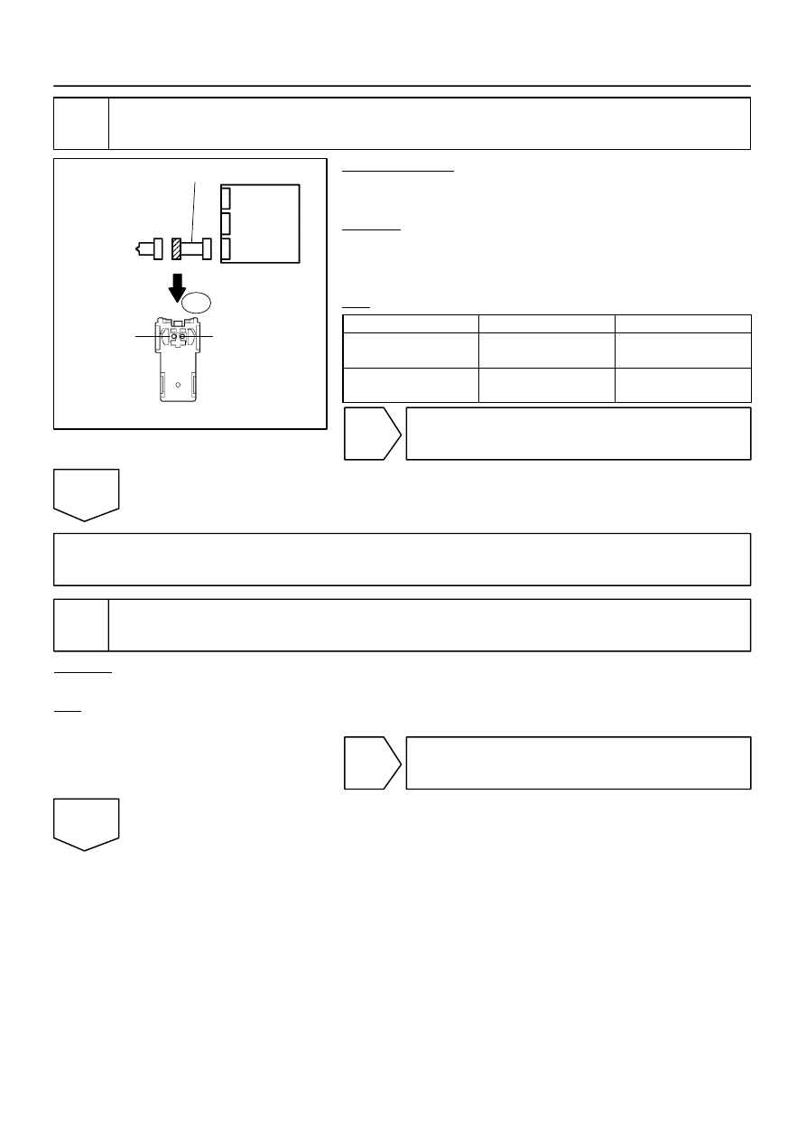
H01019
H43108
H23604
P/T Squib RH
PR–
PR+
Airbag
Sensor
Assembly
Floor Wire
B
C
D
A
P11
–
DIAGNOSTICS
SUPPLEMENTAL RESTRAINT SYSTEM
DI–1463
1657
6
Check floor wire (short to B+).
PREPARATION:
Connect the negative (–) terminal cable to the battery, and wait
for at least 2 seconds.
CHECK:
(a)
Turn the ignition switch to the ON position.
(b)
Measure the voltage according to the value(s) in the table
below.
OK:
Tester Connection
Condition
Specified Condition
P11–1 (PR+) –
Body ground
Ignition switch ON
Below 1 V
P11–2 (PR–) –
Body ground
Ignition switch ON
Below 1 V
NG
Repair or replace floor wire.
OK
Go to step 11.
7
Check connector.
CHECK:
Check that the floor wire connector (on the front seat outer belt RH side) is not damaged.
OK:
The lock button is not disengaged, or the claw of the lock is not deformed or damaged.
NG
Repair or replace floor wire.
OK
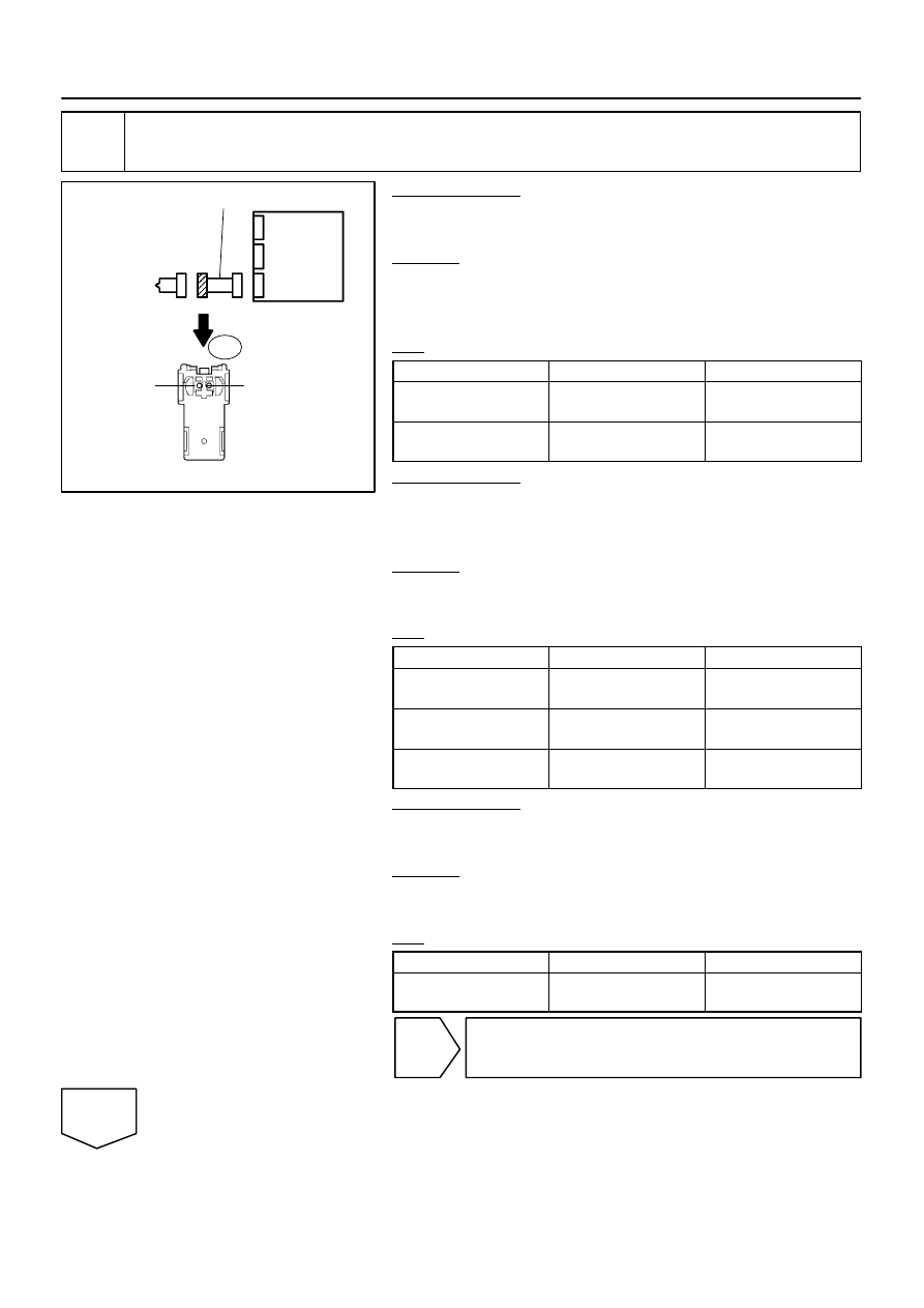
H01019
H43108
H23604
P/T Squib RH
PR–
PR+
Airbag
Sensor
Assembly
Floor Wire
B
C
D
A
P11
DI–1464
–
DIAGNOSTICS
SUPPLEMENTAL RESTRAINT SYSTEM
1658
8
Check floor wire (P/T squib RH circuit).
PREPARATION:
Connect the negative (–) terminal cable to the battery, and wait
for at least 2 seconds.
CHECK:
(a)
Turn the ignition switch to the ON position.
(b)
Measure the voltage according to the value(s) in the table
below.
OK:
Tester Connection
Condition
Specified Condition
P11–1 (PR+) –
Body ground
Ignition switch ON
Below 1 V
P11–2 (PR–) –
Body ground
Ignition switch ON
Below 1 V
PREPARATION:
(a)
Turn the ignition switch to the LOCK position.
(b)
Disconnect the negative (–) terminal cable from the bat-
tery, and wait for at least 90 seconds.
CHECK:
Measure the resistance according to the value(s) in the table
below.
OK:
Tester Connection
Condition
Specified Condition
P11–1 (PR+) –
P11–2 (PR–)
Always
Below 1
Ω
P11–1 (PR+) –
Body ground
Always
1 M
Ω
or higher
P11–2 (PR–) –
Body ground
Always
1 M
Ω
or higher
PREPARATION:
Release the activation prevention mechanism built into con-
nector ”B” (see page
CHECK:
Measure the resistance according to the value(s) in the table
below.
OK:
Tester Connection
Condition
Specified Condition
P11–1 (PR+) –
P11–2 (PR–)
Always
1 M
Ω
or higher
NG
Repair or replace floor wire.
OK
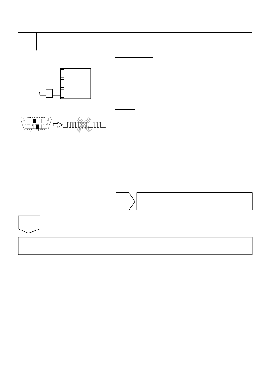
H10600
H01021
H01086
H24655
DLC3
CG
TC
P/T Squib RH
C
D
Airbag
Sensor
Assembly
DTC 73
–
DIAGNOSTICS
SUPPLEMENTAL RESTRAINT SYSTEM
DI–1465
1659
9
Replace front seat outer belt RH (P/T squib RH).
PREPARATION:
(a)
Replace the front seat outer belt RH (see page
HINT:
Perform the inspection using parts from a normal vehicle if pos-
sible.
(b)
Connect the connectors to the airbag sensor assembly.
(c)
Connect the negative (–) terminal cable to the battery,
and wait for at least 2 seconds.
CHECK:
(a)
Turn the ignition switch to the ON position, and wait for at
least 60 seconds.
(b)
Clear the DTCs stored in memory (see page
(c)
Turn the ignition switch to the LOCK position.
(d)
Turn the ignition switch to the ON position, and wait for at
least 60 seconds.
(e)
OK:
DTC 73 is not output.
HINT:
Codes other than DTC 73 may be output at this time, but they
are not related to this check.
NG
Replace airbag sensor assembly
(see page
).
OK
END
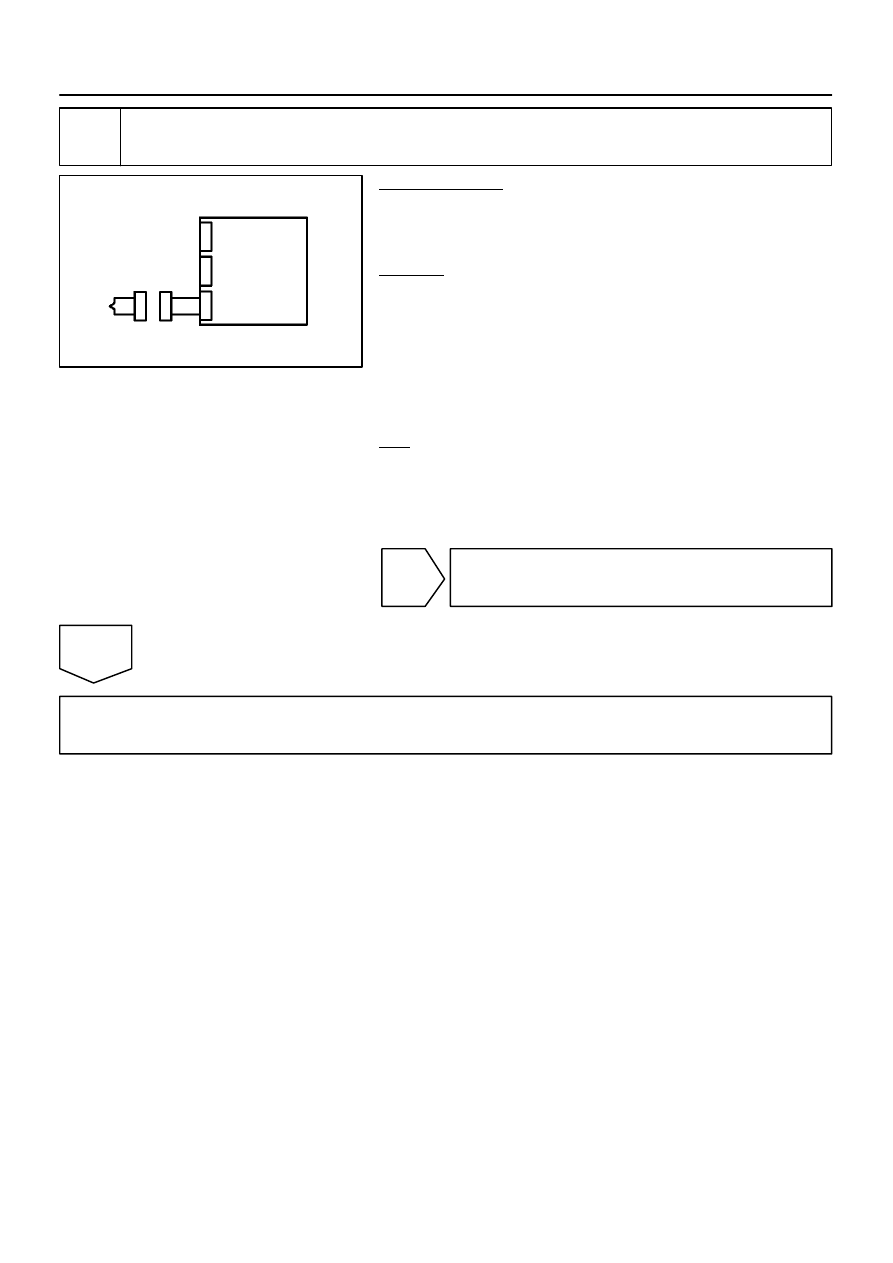
H01017
H23588
Airbag
Sensor
Assembly
C
D
P/T Squib RH
DI–1466
–
DIAGNOSTICS
SUPPLEMENTAL RESTRAINT SYSTEM
1660
10
Check airbag sensor assembly.
PREPARATION:
(a)
Connect the connectors to the airbag sensor assembly.
(b)
Connect the negative (–) terminal cable to the battery,
and wait for at least 2 seconds.
CHECK:
(a)
Turn the ignition switch to the ON position, and wait for at
least 60 seconds.
(b)
Clear the DTCs stored in memory (see page
(c)
Turn the ignition switch to the LOCK position.
(d)
Turn the ignition switch to the ON position, and wait for at
least 60 seconds.
(e)
OK:
DTC B1900 is not output.
HINT:
Codes other than DTC B1900 may be output at this time, but
they are not related to this check.
NG
Replace airbag sensor assembly
(see page
).
OK
Go to step 12.
Нет комментариевНе стесняйтесь поделиться с нами вашим ценным мнением.
Текст