Toyota Sequoia (2005). Manual — part 415
H01017
H23472
Airbag
Sensor
Assembly
Curtain Shield
Airbag LH Squib
D
C
–
DIAGNOSTICS
SUPPLEMENTAL RESTRAINT SYSTEM
DI–1455
1649
10
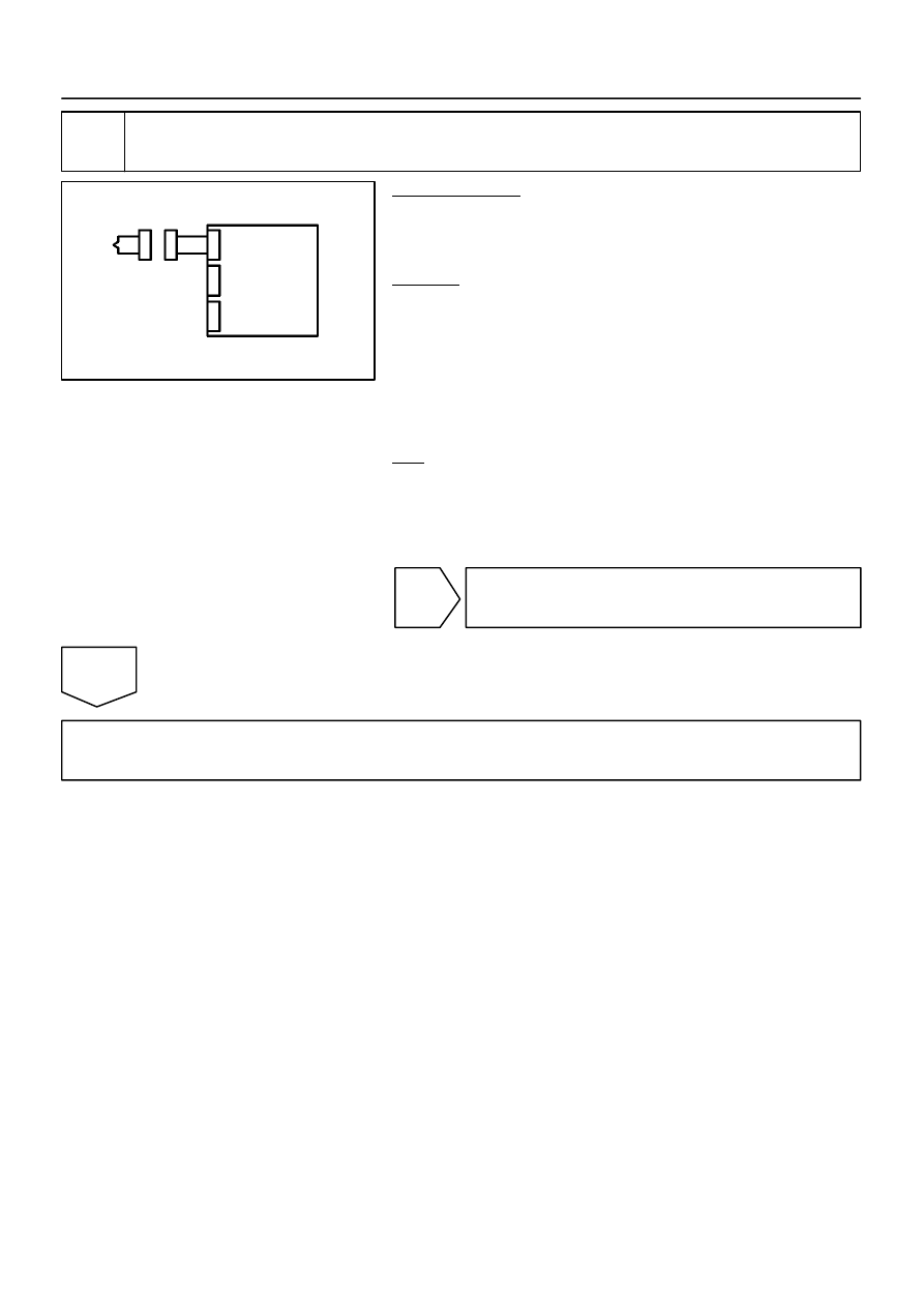
Check airbag sensor assembly.
PREPARATION:
(a)
Connect the connectors to the airbag sensor assembly.
(b)
Connect the negative (–) terminal cable to the battery,
and wait for at least 2 seconds.
CHECK:
(a)
Turn the ignition switch to the ON position, and wait for at
least 60 seconds.
(b)
Clear the DTCs stored in memory (see page
(c)
Turn the ignition switch to the LOCK position.
(d)
Turn the ignition switch to the ON position, and wait for at
least 60 seconds.
(e)
OK:
DTC B1835 is not output.
HINT:
Codes other than DTC B1835 may be output at this time, but
they are not related to this check.
NG
Replace airbag sensor assembly
(see page
).
OK
Go to step 12.
H01017
H23982
H23992
Airbag
Sensor
Assembly
ICL+
ICL–
D C
Service Wire
Curtain Shield
Airbag LH Squib
C11
DI–1456
–
DIAGNOSTICS
SUPPLEMENTAL RESTRAINT SYSTEM
1650
11
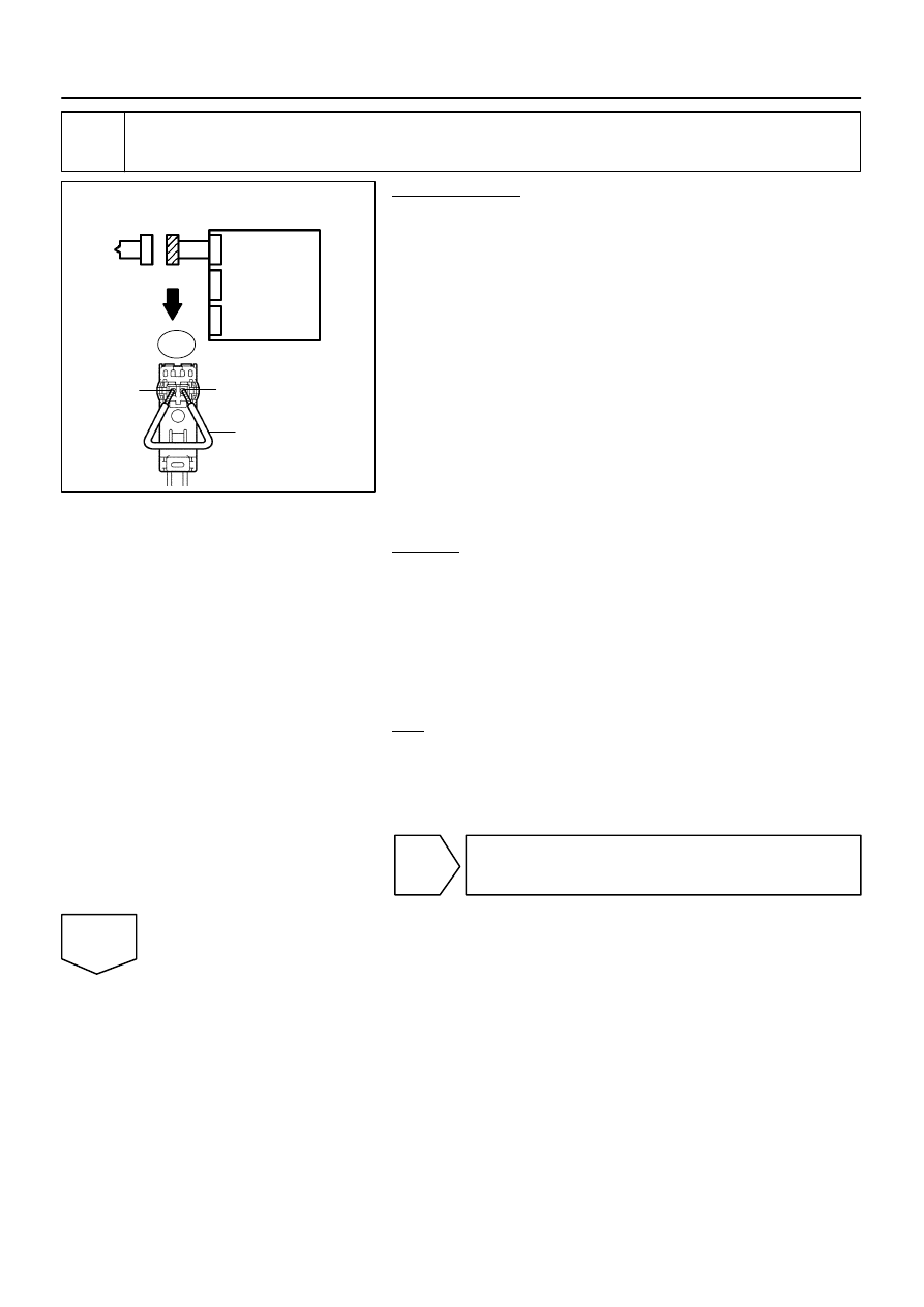
Check airbag sensor assembly.
PREPARATION:
(a)
From the step 6:
Turn the ignition switch to the LOCK position.
(b)
From the step 6:
Disconnect the negative (–) terminal cable from the bat-
tery, and wait for at least 90 seconds.
(c)
Using a service wire, connect C11–1 (ICL+) and C11–2
(ICL–) of the connector ”C”.
NOTICE:
Twist the end of the service wire in order to insert it
into the connector.
Do not forcibly insert the twisted service wire into the
terminals of the connector when connecting.
(d)
Connect the connectors to the airbag sensor assembly.
(e)
Connect the negative (–) terminal cable to the battery,
and wait for at least 2 seconds.
CHECK:
(a)
Turn the ignition switch to the ON position, and wait for at
least 60 seconds.
(b)
Clear the DTCs stored in memory (see page
(c)
Turn the ignition switch to the LOCK position.
(d)
Turn the ignition switch to the ON position, and wait for at
least 60 seconds.
(e)
OK:
DTC B1836, B1837 or B1838 is not output.
HINT:
Codes other than DTC B1836, B1837 and B1838 may be out-
put at this time, but they are not related to this check.
NG
Replace airbag sensor assembly
(see page
).
OK
H01018
H23474
Curtain Shield
Airbag LH Squib
Airbag
Sensor
Assembly
DC
–
DIAGNOSTICS
SUPPLEMENTAL RESTRAINT SYSTEM
DI–1457
1651
12
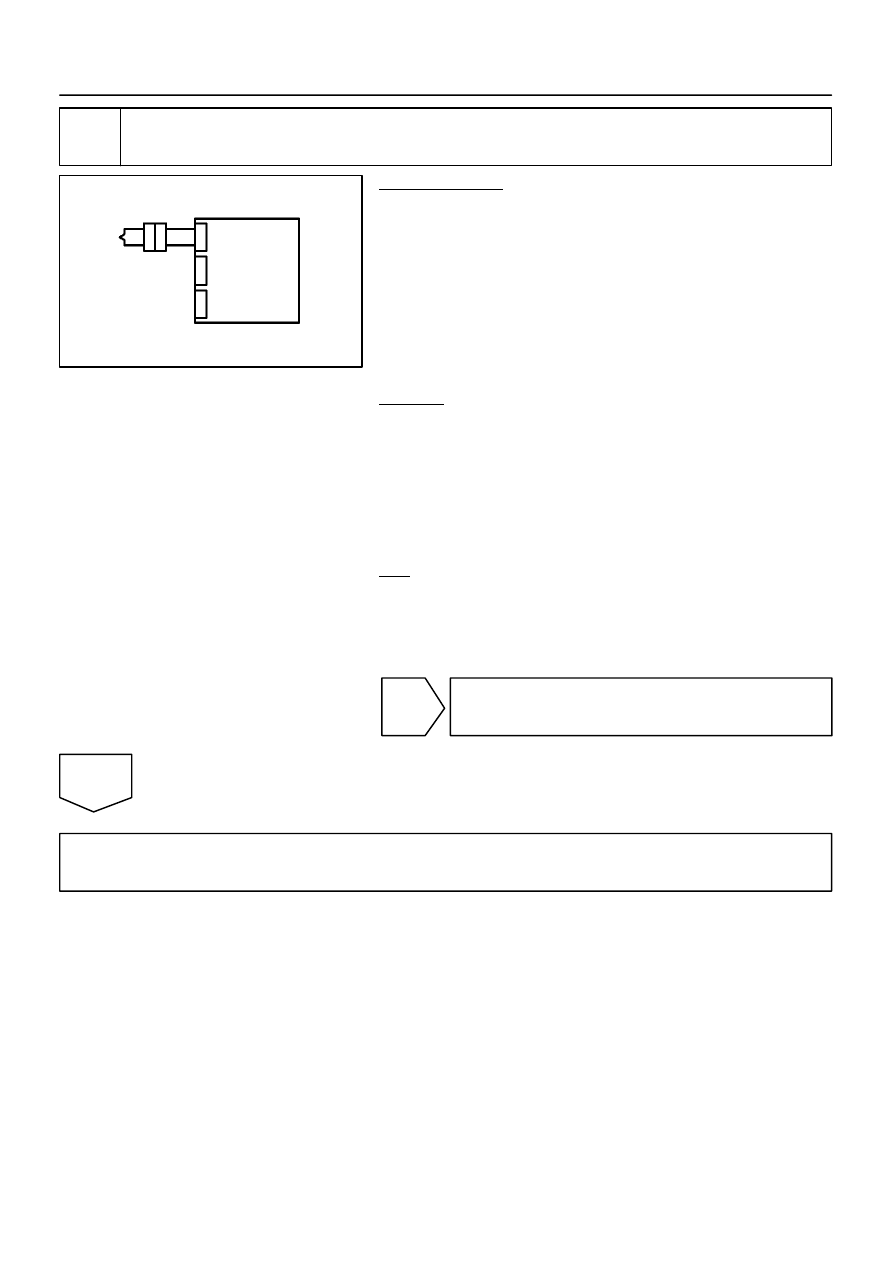
Check curtain shield airbag assembly LH (curtain shield airbag LH squib).
PREPARATION:
(a)
Turn the ignition switch to the LOCK position.
(b)
Disconnect the negative (–) terminal cable from the bat-
tery, and wait for at least 90 seconds.
(c)
From the step 9:
Disconnect the service wire from connector ”C”.
(d)
Connect the connector to the curtain shield airbag as-
sembly LH.
(e)
Connect the negative (–) terminal cable to the battery,
and wait for at least 2 seconds.
CHECK:
(a)
Turn the ignition switch to the ON position, and wait for at
least 60 seconds.
(b)
Clear the DTCs stored in memory (see page
(c)
Turn the ignition switch to the LOCK position.
(d)
Turn the ignition switch to the ON position, and wait for at
least 60 seconds.
(e)
OK:
DTC B1835, B1836, B1837 or B1838 is not output.
HINT:
Codes other than DTC B1835, B1836, B1837 and B1838 may
be output at this time, but they are not related to this check.
NG
Replace curtain shield airbag assembly LH
(see page
).
OK
From the results of the above inspection, the malfunctioning part can now be considered normal.
To make sure of this, use the simulation method to check (see page
HINT:
Perform the simulation method by selecting the check mode with the hand–held tester (see page
After selecting the check mode, perform the simulation method by wiggling each connector of the air-
bag system or driving the vehicle on a city or rough road (see page

DI–1458
–
DIAGNOSTICS
SUPPLEMENTAL RESTRAINT SYSTEM
1652
DTC
B1900/73 Short in P/T Squib (RH) Circuit
DTC
B1901/73 Open in P/T Squib (RH) Circuit
DTC
B1902/73 Short in P/T Squib (RH) Circuit (to Ground)
DTC
B1903/73 Short in P/T Squib (RH) Circuit (to B+)
CIRCUIT DESCRIPTION
The P/T squib RH circuit consists of the airbag sensor assembly and the front seat outer belt RH.
The circuit instructs the SRS to deploy when deployment conditions are met.
These DTCs are recorded when a malfunction is detected in the P/T squib RH circuit.
DTC No.
DTC Detection Condition
Trouble Area
B1900/73
The airbag sensor assembly receives a line short circuit
signal 5 times in the P/T squib RH circuit during primary
check.
P/T squib RH malfunction
Airbag sensor assembly malfunction
Front seat outer belt RH (P/T squib RH)
Airbag sensor assembly
Floor wire
B1901/73
The airbag sensor assembly receives an open circuit sig-
nal in the P/T squib RH circuit for 2 seconds.
P/T squib RH malfunction
Airbag sensor assembly malfunction
Front seat outer belt RH (P/T squib RH)
Airbag sensor assembly
Floor wire
B1902/73
The airbag sensor assembly receives a short circuit to
ground signal in the P/T squib RH circuit for 0.5 seconds.
P/T squib RH malfunction
Airbag sensor assembly malfunction
Front seat outer belt RH (P/T squib RH)
Airbag sensor assembly
Floor wire
B1903/73
The airbag sensor assembly receives a short to B+ circuit
signal in the P/T squib RH circuit for 0.5 seconds.
P/T squib RH malfunction
Airbag sensor assembly malfunction
Front seat outer belt RH (P/T squib RH)
Airbag sensor assembly
Floor wire
DIDHQ–01
Нет комментариевНе стесняйтесь поделиться с нами вашим ценным мнением.
Текст