Toyota Sequoia (2005). Manual — part 419
–
DIAGNOSTICS
SUPPLEMENTAL RESTRAINT SYSTEM
DI–1471
1665
INSPECTION PROCEDURE
CAUTION:
Be sure to perform the following procedures before troubleshooting to avoid unexpected airbag de-
ployment.
(a)
Turn the ignition switch to the LOCK position.
(b)
Disconnect the negative (–) terminal cable from the battery, and wait for at least 90 seconds.
(c)
Disconnect the connectors from the airbag sensor assembly.
(d)
Disconnect the connectors from the steering wheel pad.
(e)
Disconnect the connectors from the front passenger airbag assembly.
(f)
w/ Side and curtain shield airbag:
Disconnect the connectors from the side airbag assembly LH and RH.
(g)
w/ Side and curtain shield airbag:
Disconnect the connectors from the curtain shield airbag assembly LH and RH.
(h)
Disconnect the connectors from the front seat outer belt LH and RH.
1
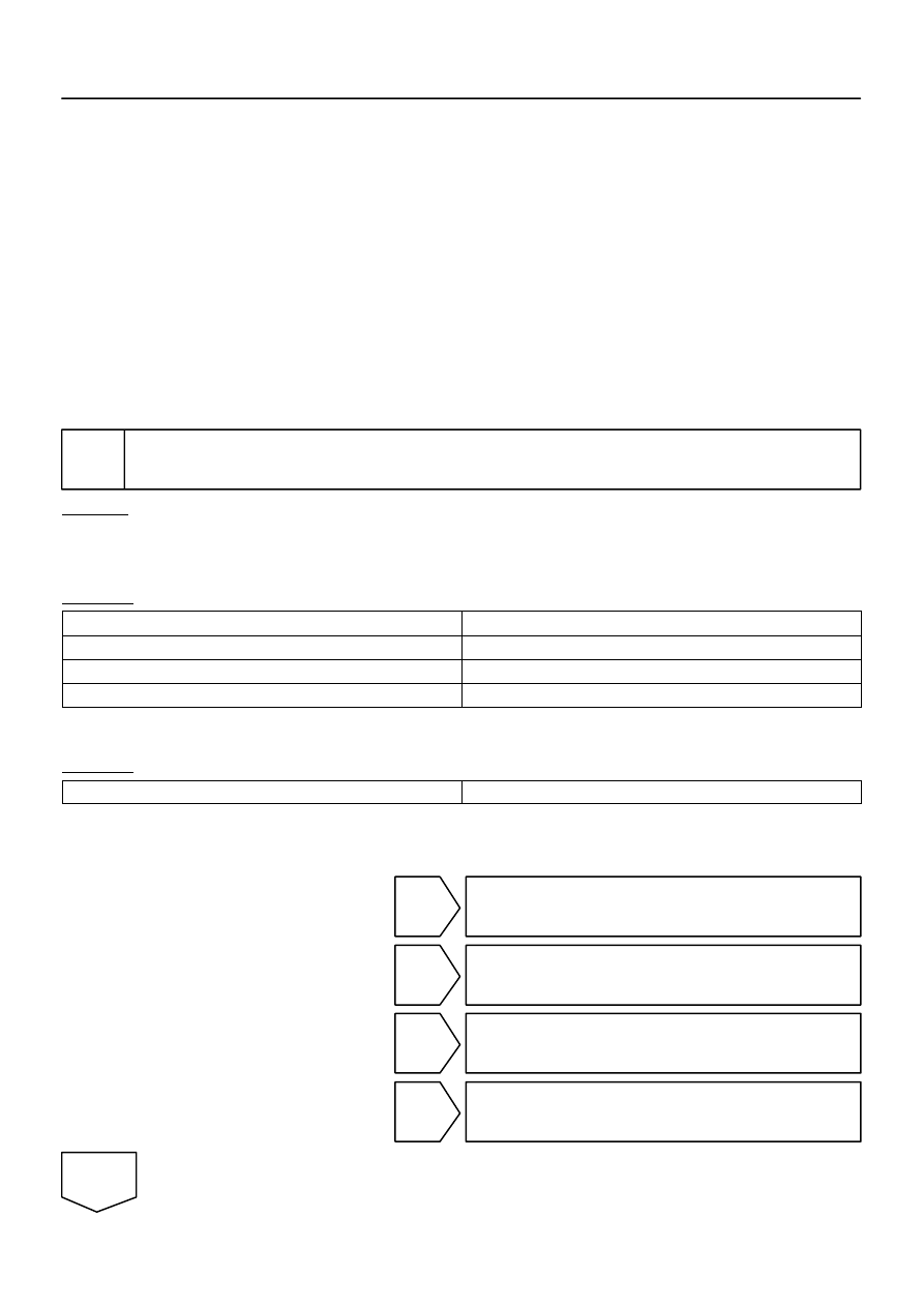
Check DTC.
CHECK:
(a)
Proceed to each step according to how to read DTC.
(1)
If using the hand–held tester (read the 5–digit of DTC):
Using the hand–held tester, check the DTCs (see page
RESULT:
DTC B1905 is output.
A
DTC B1906 is output.
B
DTC B1907 is output.
C
DTC B1908 is output.
D
(2)
If not using the hand–held tester (read the 2–digit of DTC):
Check the DTCs (see page
).
RESULT:
DTC 74 is output.
E
HINT:
Codes other than DTC B1905, B1906, B1907, B1908 and DTC 74 may be output at this time, but they are
not related to this check.
B
Go to step 4.
C
Go to step 5.
D
Go to step 6.
E
Go to step 7.
A
H01016
H43108
H23601
P/T Squib LH
PL–
PL+
Airbag
Sensor
Assembly
Floor Wire No. 2
A
B
C
D
P10
DI–1472
–
DIAGNOSTICS
SUPPLEMENTAL RESTRAINT SYSTEM
1666
2
Check connector.
CHECK:
Check that the floor wire No. 2 connector (on the front seat outer belt LH side) is not damaged.
OK:
The lock button is not disengaged, or the claw of the lock is not deformed or damaged.
NG
Repair or replace floor wire No. 2.
OK
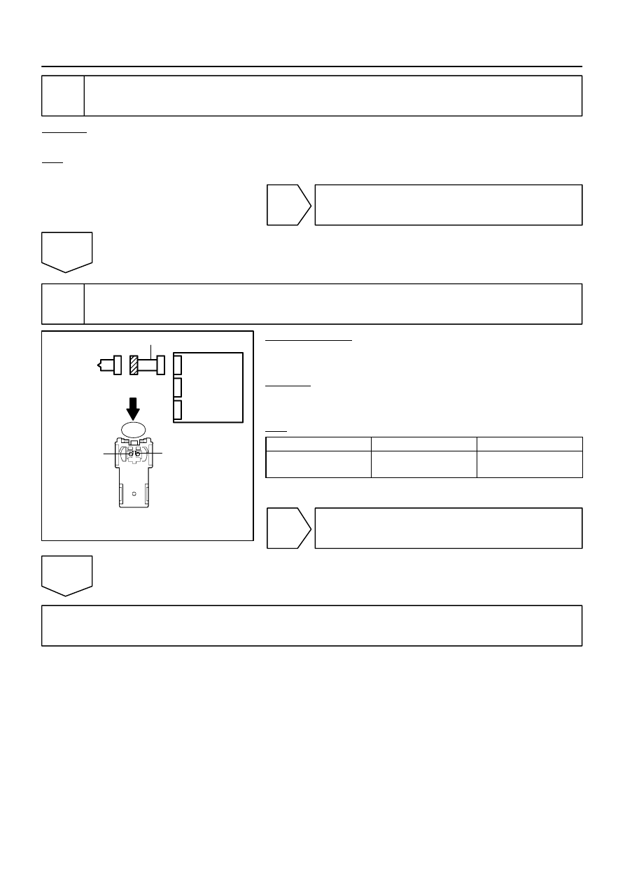
3
Check floor wire No. 2 (short).
PREPARATION:
Release the activation prevention mechanism built into con-
nector ”B” (see page
CHECK:
Measure the resistance according to the value(s) in the table
below.
OK:
Tester Connection
Condition
Specified Condition
P10–1 (PL+) –
P10–2 (PL–)
Always
1 M
Ω
or Higher
NG
Repair or replace floor wire No. 2.
OK
Go to step 10.
H01016
H43108
H23601
P/T Squib LH
PL–
PL+
Airbag
Sensor
Assembly
Floor Wire No. 2
A
B
C
D
P10
H01016
H43108
H23601
P/T Squib LH
PL–
PL+
Airbag
Sensor
Assembly
Floor Wire No. 2
A
B
C
D
P10
–
DIAGNOSTICS
SUPPLEMENTAL RESTRAINT SYSTEM
DI–1473
1667
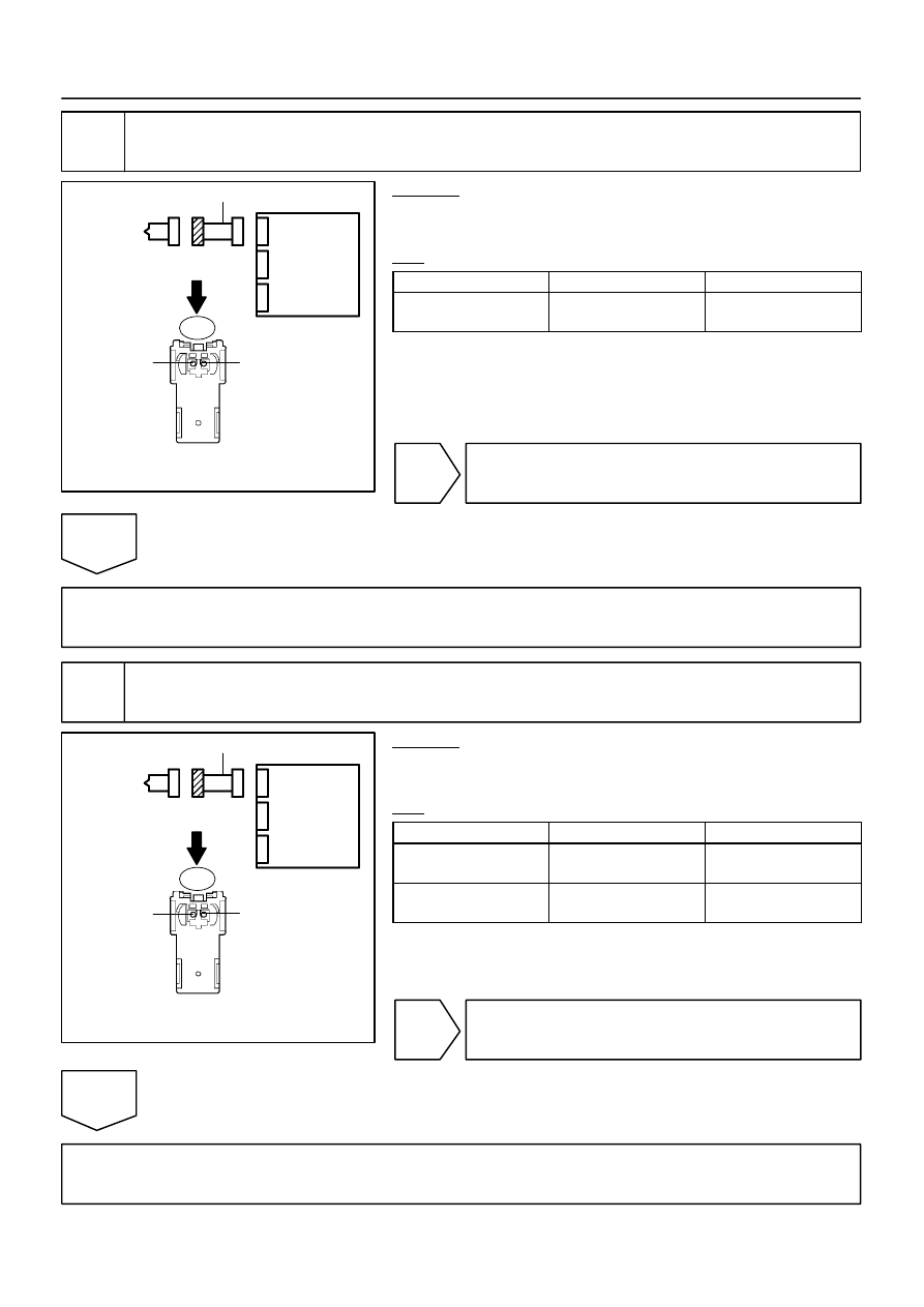
4
Check floor wire No. 2 (open).
CHECK:
Measure the resistance according to the value(s) in the table
below.
OK:
Tester Connection
Condition
Specified Condition
P10–1 (PL+) –
P10–2 (PL–)
Always
Below 1
Ω
NG
Repair or replace floor wire No. 2.
OK
Go to step 11.
5
Check floor wire No. 2 (short to ground).
CHECK:
Measure the resistance according to the value(s) in the table
below.
OK:
Tester Connection
Condition
Specified Condition
P10–1 (PL+) –
Body ground
Always
1 M
Ω
or higher
P10–2 (PL–) –
Body ground
Always
1 M
Ω
or higher
NG
Repair or replace floor wire No. 2.
OK
Go to step 11.
H01016
H43108
H23601
P/T Squib LH
PL–
PL+
Airbag
Sensor
Assembly
Floor Wire No. 2
A
B
C
D
P10
DI–1474
–
DIAGNOSTICS
SUPPLEMENTAL RESTRAINT SYSTEM
1668
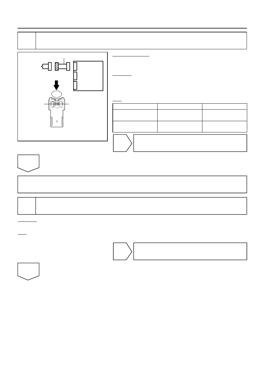
6
Check floor wire No. 2 (short to B+).
PREPARATION:
Connect the negative (–) terminal cable to the battery, and wait
for at least 2 seconds.
CHECK:
(a)
Turn the ignition switch to the ON position.
(b)
Measure the voltage according to the value(s) in the table
below.
OK:
Tester Connection
Condition
Specified Condition
P10–1 (PL+) –
Body ground
Ignition switch ON
Below 1 V
P10–2 (PL–) –
Body ground
Ignition switch ON
Below 1 V
NG
Repair or replace floor wire No. 2.
OK
Go to step 11.
7
Check connector.
CHECK:
Check that the floor wire No. 2 connector (on the front seat outer belt LH side) is not damaged.
OK:
The lock button is not disengaged, or the claw of the lock is not deformed or damaged.
NG
Repair or replace floor wire No. 2.
OK
Нет комментариевНе стесняйтесь поделиться с нами вашим ценным мнением.
Текст