Toyota Sequoia (2005). Manual — part 858
I28399
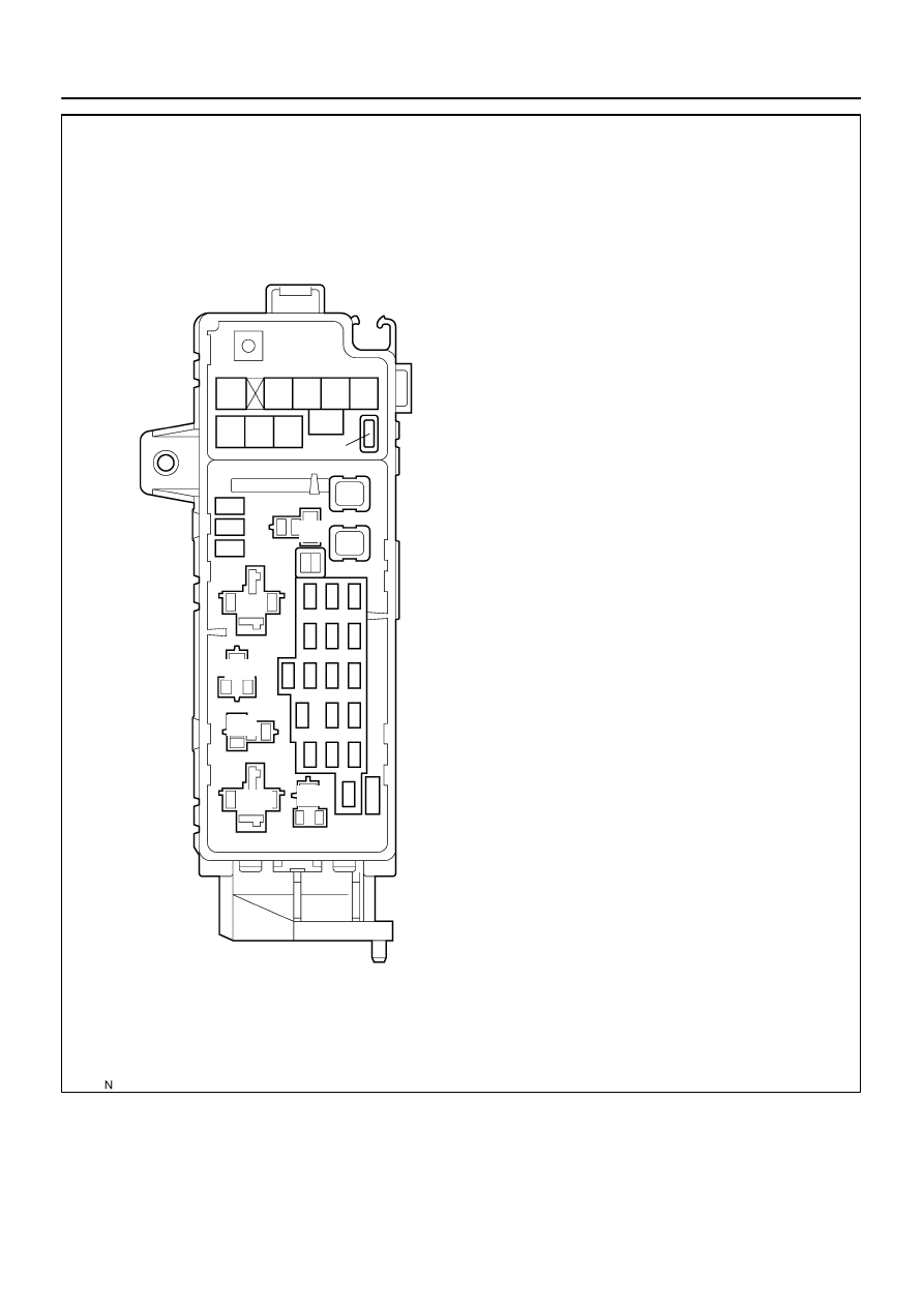
Fusible Link Block:
Relays:
Fuses:
5. RR HEATER Fuse 30 A
A. C/OPN Relay
B. HEAD Relay
C. EFI Relay
D. FUEL PUMP Relay
E. DEFOG Relay
F. HORN Relay
Engine Room J/B
6. R/B Fuse 30 A
7. A/PUMP Fuse 50 A
8. ABS Fuse 60 A
9. ALT Fuse 140 A
10. CDS FAN Fuse 25 A
11. Spare Fuse 15 A
12. Spare Fuse 20 A
13. Spare Fuse 30 A
14. Main Fuse 40 A
15. DOOR No. 2 Fuse 30 A
16. *2 H–LP RH Fuse 15 A
17. EFI No. 1 Fuse 20 A
18. ETCS Fuse 10 A
19. *1.DRL Fuse 15 A
*2.H–LP LH Fuse 15 A
20. ALT–S Fuse 7.5 A
21. TOWING Fuse 30 A
22. ST Fuse 30 A
23. RAD No. 3 Fuse 30 A
24. TURN–HAZ Fuse 20 A
25. AM2 Fuse 25 A
26. EFI No. 2 Fuse 10 A
27. SHORT–PIN
28. HORN Fuse 10 A
29. MIR HTR Fuse 15 A
30. ECU–B Fuse 7.5 A
31. DOME Fuse 10 A
32. RAD No. 1 Fuse 20 A
*1 w/ Daytime Running Light
*2 w/o Daytime Running Light
15
16
17
18
19
20
21
26
27
28
29
30
A
B
C
D
E
F
1
2
3
4
5
6
7
8
9
10
22
23
24
25
31
32
11
12
13
14
1. TOWING R/B Fuse 50 A
2. AIR SUS Fuse 50 A
3. HEATER Fuse 50 A
4. DEFOG Fuse 40 A
–
BODY ELECTRICAL
POWER SOURCE
BE–17
3421
I28550
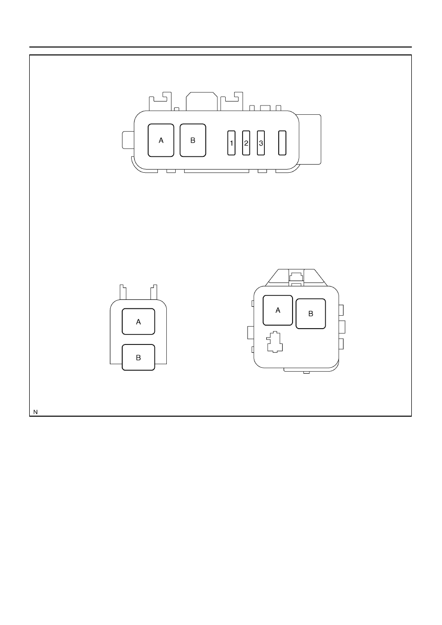
Engine Room R/B No. 3:
Relays:
Fuses:
1. TOWING BRK Fuse 30 A
A. BATT CHARGE Relay
B. TOWING TAIL Relay
2. BATT CHARGE Fuse 30 A
3. TOWING TAIL Fuse 30 A
Driver Side R/B:
Relays:
A. INVERTER Relay
B. SEAT HEATER Relay
Engine Room R/B No. 4:
Relays:
A. RR HEATER Relay
B. HEATER Relay
BE–18
–
BODY ELECTRICAL
POWER SOURCE
3422
BE2DE–03
I28400
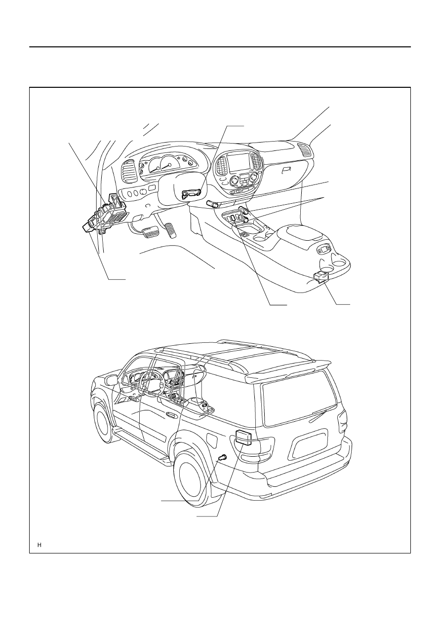
Power Outlet (12 V)
Power Outlet
(115 V) (*1)
(12 V) (*2)
Ignition Switch
Main Switch
Instrument Panel J/B
IPO (Intelligent Power Outlet)
AC INV Fuse
Driver Side R/B
INVERTER Relay
PWR OUTLET Fuse
Power Outlet (12 V)
*1: w/ Rear Seat Entertainment System
w/ Rear Seat Audio System
*2: w/o Rear Seat Entertainment System
w/o Rear Seat Audio System
Voltage Inverter
(Located inside of the
quarter trim panel LH)
Cigarette Lighter
–
BODY ELECTRICAL
POWER OUTLET
BE–19
3423
POWER OUTLET
LOCATION
BE2MU–01
I27713
I27712
I05027
3
1
5
2
5
2
3
1
I24374
Wire Harness Side:
BE–20
–
BODY ELECTRICAL
POWER OUTLET
3424
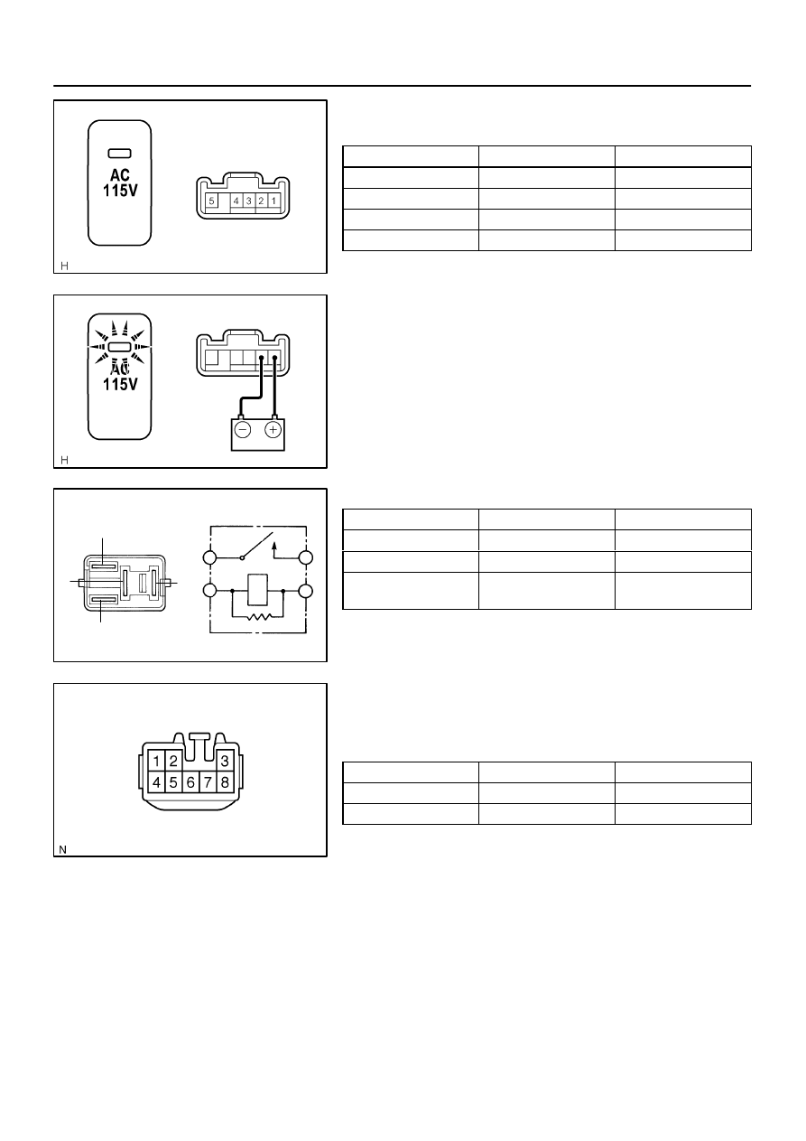
INSPECTION
1.
INSPECT MAIN SWITCH CONTINUITY
Switch position
Tester connection
Specified condition
ON
3 – 5
Continuity
OFF
3 – 5
No continuity
Constant
4 – 5
Continuity
Illumination circuit
1 – 2
Continuity
If continuity is not as specified, replace the switch.
2.
INSPECT MAIN INDICATOR LIGHT OPERATION
(a)
Connect the positive (+) lead from the battery to terminal
1 and the negative (–) lead to terminal 2.
(b)
Push the main switch and check that the indicator light
comes on.
If operation is not as specified, replace the switch.
3.
INSPECT INVERTER RELAY CONTINUITY
Condition
Tester connection
Specified condition
Constant
1 – 2
Continuity
Constant
3 – 5
No continuity
Apply B+ between
terminals 1 and 2
3 – 5
Continuity
If continuity is not as specified, replace the relay.
4.
INSPECT VOLTAGE INVERTER CIRCUIT
Disconnect the connector from the voltage inverter and inspect
the connector on the wire harness side as shown in the table
below.
Switch position
Tester connection
Specified condition
ON
1 – 4
Battery positive voltage
OFF
1 – 4
No voltage
If the circuit is not as specified, inspect the circuits connected
to other parts.
Нет комментариевНе стесняйтесь поделиться с нами вашим ценным мнением.
Текст