Toyota Sequoia (2005). Manual — part 593
I28190
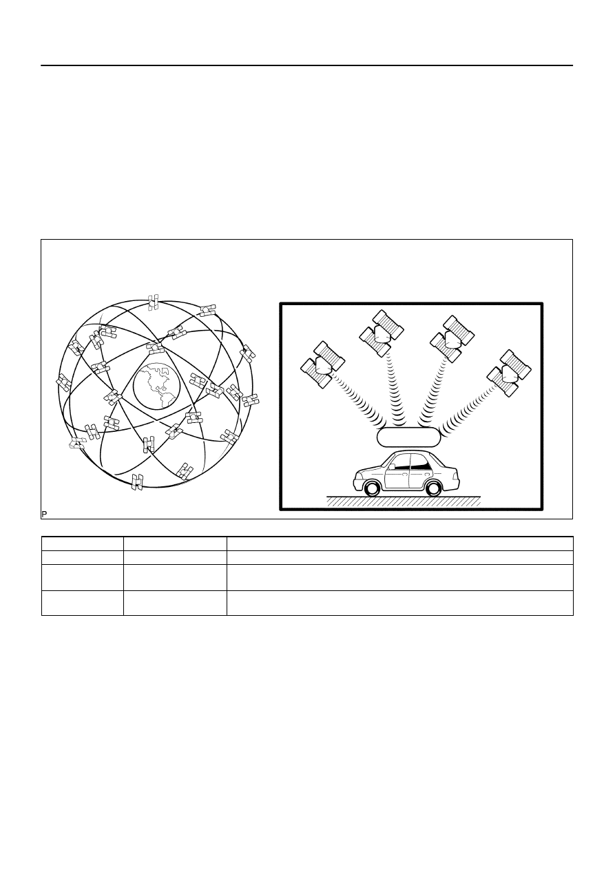
GPS
Current longitude/latitude/altitude is determined using the radio wave arrival time from four satellites.
–
DIAGNOSTICS
NAVIGATION SYSTEM
DI–2167
2361
(b)
Autonomous navigation
This method determines the relative vehicle position based on the running track determined by the
gyro and vehicle speed sensors located in the navigation ECU.
(1)
Gyro sensor
Calculates the direction by detecting angular velocity. It is located in the radio and navigation
assy.
(2)
Vehicle speed sensor
Used to calculate the vehicle running distance.
(c)
GPS navigation (Satellite navigation)
This method detects the absolute vehicle position using radio wave from a GPS satellite.
* GPS satellites were launched by the U.S. Department of Defence for military purposes.
Number of satellites
Measurement
Description
2 or less
Measurement impossible
Vehicle position cannot be obtained because the number of satellites is not enough.
3
2–dimensional measure-
ment is possible
Vehicle position is obtained based on the current longitude and latitude (This is less precise
than 3–dimensional measurement).
4
3–dimensional measure-
ment is possible
Vehicle position is obtained based on the current longitude, latitude and altitude.
I28191
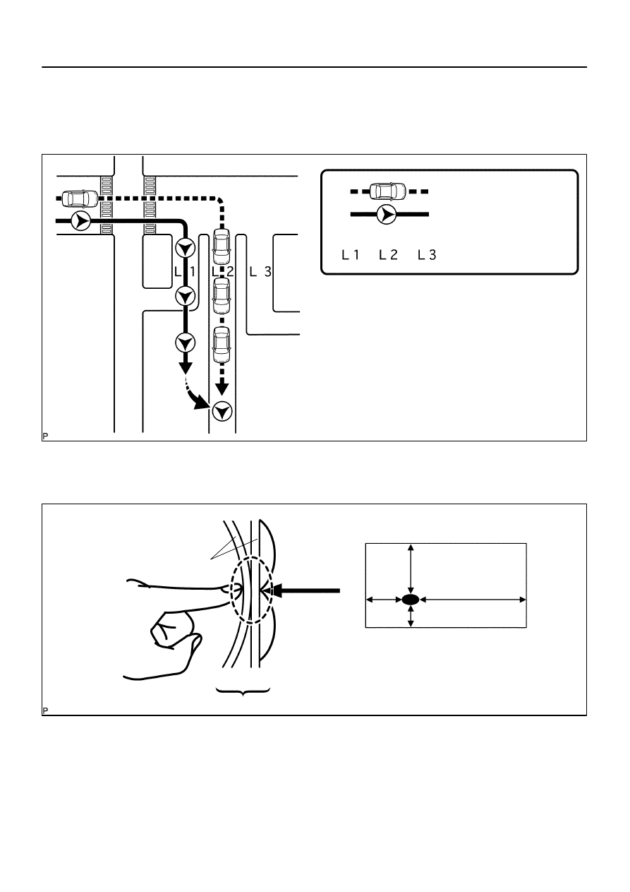
A
Actual driving route
Driving route on the display
(Route by estimation)
Roads
The system compares the shape of the roads L1,
L2 and L3 to the estimated running track after the
vehicle makes a right turn. At point A, the vehicle
position differs enough from the shape of L1 that
the display switches to the road L2.
Start
Map
Matching
I28192
Vy1
Vx1
Vx2
Vy2
Vx1 (Vy1)
Vx2 (Vy2)
Touch–sensitive switch position
The touch switch detects the voltage ratio
and calculates the position on the screen.
Glass
Outer
Inner
Contact
DI–2168
–
DIAGNOSTICS
NAVIGATION SYSTEM
2362
(d)
Map matching
The current driving route is calculated by autonomous navigation (according to the gyro sensor and
vehicle speed sensor) and GPS navigation. This information is then compared with possible road
shapes from the map data in the map disc and the vehicle position is set onto the most appropriate
road.
(e)
Touch switch
Touch switches are touch–sensitive (interactive) switches operated by touching the screen. When a
switch is pressed, the outer glass bends in to contact the inner glass at the pressed position. By doing
this, the voltage ratio is measured and the pressed position is detected.
–
DIAGNOSTICS
NAVIGATION SYSTEM
DI–2169
2363
4.
DVD (Digital Versatile Disc) player outline (for navigation map)
The navigation ECU uses a laser pickup to read the digital signals recorded on a DVD.
HINT:
Do not disassemble any part of the navigation system.
Do not apply oil to the navigation system.
Do not insert anything but a DVD into the navigation system.
CAUTION:
Because the navigation system uses an invisible laser beam, do not look directly at the laser pickup.
Be sure to only operate the navigation as instructed.
5.
CD (Compact Disc) player outline
A CD player uses a laser pickup to read digital signals recorded on a CD. By converting the digital signals
to analog, it can play music and other things. In general, CD players can play a 4.7–inch (12 cm) or 3.2–inch
(8 cm) disc.
HINT:
Do not disassemble any part of the CD player.
Do not apply oil to the CD player.
Do not insert anything but a CD into the CD player.
CAUTION:
Because the CD player uses an invisible laser beam, do not look directly at the laser pickup. Be sure
to only operate the player as instructed.
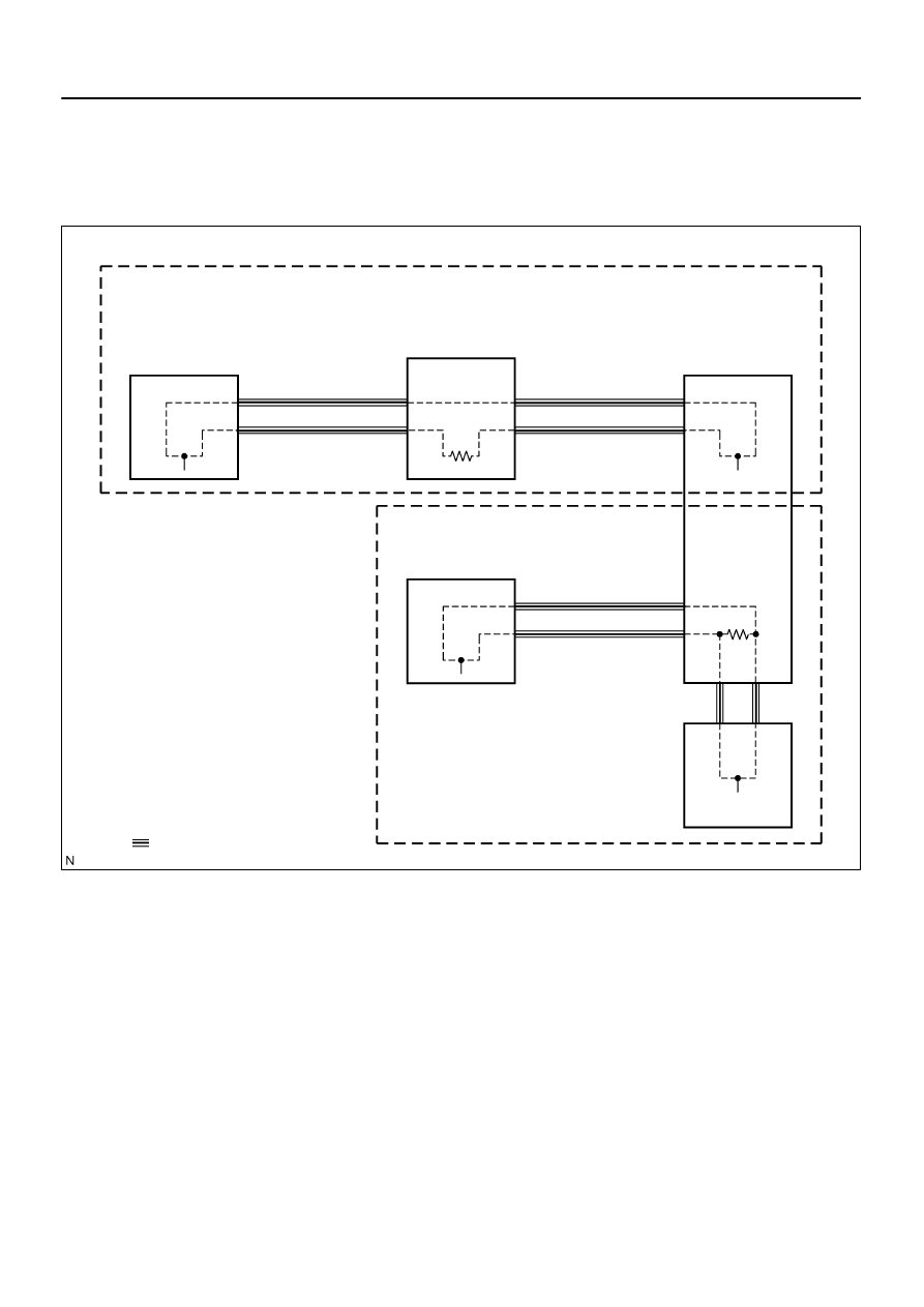
I28687
Main AVC–LAN:
(*1, 2)
Multi–display Controller
Sub–assy (*1)
Rear Seat Audio
Controller (*2)
Radio and Navigation Assy
Stereo Component
Amplifier Assy
Sub AVC–LAN:
Disc Player
Controller (*1)
Television Display Assy (*1)
*1 w/ RSE
*2: w/ RSA
: AVC–LAN
DI–2170
–
DIAGNOSTICS
NAVIGATION SYSTEM
2364
6.
AVC–LAN Description
(a)
What is AVC–LAN?
AVC–LAN, an abbreviation for ”Audio Visual Communication Local Area Network”, is a united standard
developed by the manufacturers in affiliation with Toyota Motor Corporation. This standard pertains
to audio and visual signals as well as switch and communication signals.
(b)
Purpose:
Recently, car audio systems have rapidly developed and the functions vastly changed. The conven-
tional car audio system is being integrated with multi–media interfaces similar to those in navigation
systems. At the same time, customers are demanding higher quality from their audio systems. This
is merely an overview of the standardization background. The specific purposes are as follows.
(1)
To solve sound problems, etc. caused by using components of different manufacturers through
signal standardization.
(2)
To allow each manufacturer to concentrate on developing products they do best. From this, rea-
sonably priced products can be produced.
Нет комментариевНе стесняйтесь поделиться с нами вашим ценным мнением.
Текст