Toyota Sequoia (2005). Manual — part 508
–
DIAGNOSTICS
PASSENGER DOOR CONTROL SYSTEM
DI–1827
2021
INSPECTION PROCEDURE
1
Check ECU–IG, AM1, PWR No. 5 and ECU–B fuse.
CHECK:
Check continuity of the ECU–IG, AM1, PWR No. 5 and ECU–B fuse.
OK:
Continuity
NG
Replace the faulty fuse.
OK
2
Check voltage between terminals BDR, CPUB, SIG and GND of passenger door
ECU connector.
PREPARATION:
Turn the ignition switch ON.
CHECK:
Measure the voltage between terminals SIG and GND of the passenger door ECU of the wire harness side
connector.
OK:
Voltage: 10 to 14 V
PREPARATION:
(a)
Turn the ignition switch OFF.
(b)
Disconnect the passenger door ECU connector.
CHECK:
Measure the voltage between terminals BDR, CPUB and GND of the passenger door ECU of the wire har-
ness side connector.
OK:
Voltage: 10 to 14 V
OK
Proceed to next circuit inspection shown in
problem symptoms table (See page
NG
DI–1828
–
DIAGNOSTICS
PASSENGER DOOR CONTROL SYSTEM
2022
3
Check wire harness and connector between passenger door ECU and battery
(See page
).
NG
Repair or replace wire harness or connector.
OK
4
Check wire harness and connector between passenger door ECU and body
ground (See page
).
NG
Repair or replace wire harness or connector.
OK
Proceed to next circuit inspection shown in
problem symptoms table
(See page
I28437
D21
Door Unlock Detection
SW Front RH
3
R–Y
4
LSWP
LSWE
W–B
4
Front Passenger
Door ECU
13
24
9
F18 F18
F18 F18
*1: w/ Driving Position Memory
*2: w/o Driving Position Memory
(*1) (*2)
(*1) (*2)
–
DIAGNOSTICS
PASSENGER DOOR CONTROL SYSTEM
DI–1829
2023
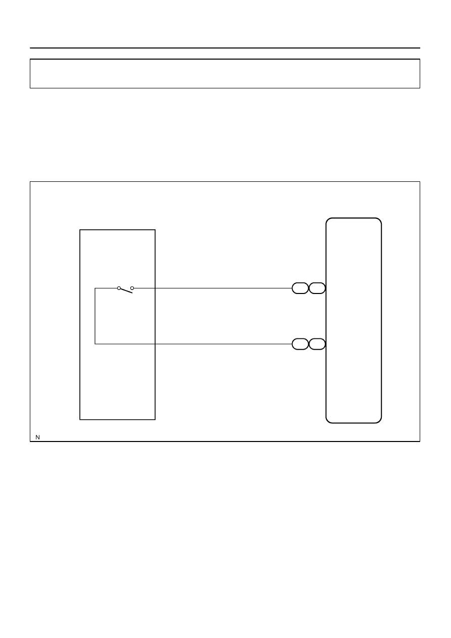
Door unlock detection switch circuit
CIRCUIT DESCRIPTION
The door unlock detection switch is built in the door lock motor. This switch is ON when the door lock knob
is in the unlock position and OFF when the lock knob is in the lock position. The ECU detects the door lock
knob conditions in this circuit. It is used as one of the operating conditions for the key confinement prevention
function.
WIRING DIAGRAM
DI1Q8–09
DI–1830
–
DIAGNOSTICS
PASSENGER DOOR CONTROL SYSTEM
2024
INSPECTION PROCEDURE
HINT:
When using the hand–held tester, start the inspection from step 1 and when not using the hand–held tester,
start from step 2.
1
Check door unlock detection switch using hand–held tester.
PREPARATION:
(a)
Connect the hand–held tester to the DLC3.
(b)
Turn the ignition switch ON.
CHECK:
According to the display on the tester, read the DATA LIST.
P–DOOR:
Item
Measurement Item/Dis-
play (Range)
Normal condition
Diagnostic Note
LOCK POS SW
Lock position SW signal/
ON or OFF
ON: Door lock is in unlock position
OFF: Door lock is in lock position
–
OK:
Indication on the tester switches between ON and OFF in accordance with the door unlock
detection switch status.
OK
Proceed to next circuit inspection shown in
problem symptoms table (See page
NG
2
Check door unlock detection switch (See page
NG
Replace the door lock assembly.
OK
Нет комментариевНе стесняйтесь поделиться с нами вашим ценным мнением.
Текст