Toyota Sequoia (2005). Manual — part 506

DIDET–01
I18630
F18
PASSENGER DOOR ECU
(w/o Driving Position Memory):
–
DIAGNOSTICS
PASSENGER DOOR CONTROL SYSTEM
DI–1819
2013
TERMINALS OF ECU
Symbols (Terminal No.)
Wiring Color
Terminal De-
scription
Condition
Specified Condition
BDR
↔
GND
(20
↔
8)
L–Y
↔
W–B
Battery
Always
10 to 14 V
CPUB
↔
GND
(12
↔
8)
W–R
↔
W–B
Battery
Always
10 to 14 V
SIG
↔
GND
(19
↔
8)
B–R
↔
W–B
Ignition switch
Ignition switch ON
10 to 14 V
GND
↔
Body Ground
(8
↔
Body ground)
W–B
↔
Body
Ground
Ground
Always
Below 1 V
PLS
↔
SGND
(17
↔
18)
L–R
↔
W–B
Power window
pulse sensor
Power window is operated
Pulse generation
PLS
↔
SGND
(17
↔
18)
L–R
↔
W–B
Power window
pulse sensor
Power window is not operated (Switch ON)
Below 1 V
PLS
↔
SGND
(17
↔
18)
L–R
↔
W–B
Power window
pulse sensor
Power window is not operated (Switch OFF)
10 to 14 V
LMT
↔
SGND
(16
↔
18)
L–W
↔
W–B
Power window
limit switch
Front passenger’s door window not fully closed position
Below 1 V
LMT
↔
SGND
(16
↔
18)
L–W
↔
W–B
Power window
limit switch
Front passenger’s door window fully closed position
10 to 14 V
PU
↔
PDN
(1
↔
9)
R
↔
G
Power window
motor (UP)
Ignition switch ON and front passenger’s window switch
OFF
Below 1 V
PU
↔
PDN
(1
↔
9)
R
↔
G
Power window
motor (UP)
Ignition switch ON and front passenger’s window switch
UP
10 to 14 V
PDN
↔
PU
(9
↔
1)
G
↔
R
Power window
motor (DOWN)
Ignition switch ON and front passenger’s window switch
OFF
Below 1 V
PDN
↔
PU
(9
↔
1)
G
↔
R
Power window
motor (DOWN)
Ignition switch ON and front passenger’s window switch
DOWN
10 to 14 V
MPX1
↔
–
(10
↔
–)
B
↔
–
Multiplex com-
munication line
Multiplex communication circuit
–
MPX2
↔
–
(11
↔
–)
G–B
↔
–
Multiplex com-
munication line
Multiplex communication circuit
–
I18633
F18
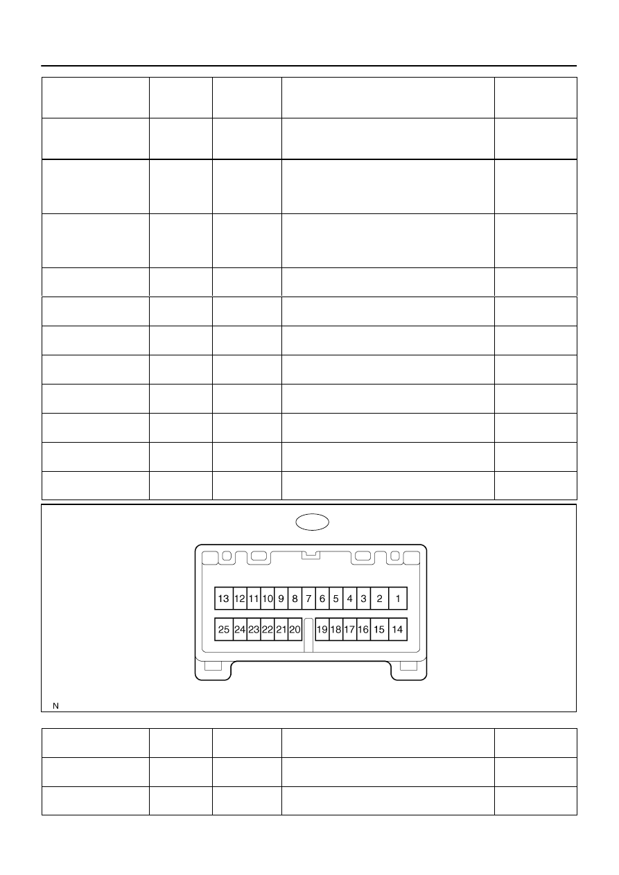
PASSENGER DOOR ECU
(w/ Driving Position Memory):
DI–1820
–
DIAGNOSTICS
PASSENGER DOOR CONTROL SYSTEM
2014
PKL
↔
LSWE
(3
↔
13)
LG–B
↔
W–B
Door key lock
and unlock
switch (LOCK)
Door key lock and unlock switch LOCK
Below 1 V
PKL
↔
LSWE
(3
↔
13)
LG–B
↔
W–B
Door key lock
and unlock
switch (LOCK)
Door key lock and unlock switch OFF or UNLOCK
10 to 14 V
PKUL
↔
LSWE
(2
↔
13)
LG–R
↔
W–B
Door key lock
and unlock
switch (UN-
LOCK)
Door key lock and unlock switch UNLOCK
Below 1 V
PKUL
↔
LSWE
(2
↔
13)
LG–R
↔
W–B
Door key lock
and unlock
switch (UN-
LOCK)
Door key lock and unlock switch OFF or LOCK
10 to 14 V
LSWP
↔
LSWE
(4
↔
13)
R–Y
↔
W–B
Door unlock
detection switch
Front passenger’s door is locked
10 to 14 V
LSWP
↔
LSWE
(4
↔
13)
R–Y
↔
W–B
Door unlock
detection switch
Front passenger’s door is unlocked
Below 1 V
LSW
↔
GND
(7
↔
8)
R–L
↔
W–B
Window lock
switch
Window lock switch position UNLOCK
Below 1 V
LSW
↔
GND
(7
↔
8)
R–L
↔
W–B
Window lock
switch
Window lock switch position LOCK
10 to 14 V
CTYB
↔
PCYL
(6
↔
5)
R
↔
R–W
Door courtesy
light (Front RH)
Front passenger’s door closed
10 to 14 V
CTYB
↔
PCYL
(6
↔
5)
R
↔
R–W
Door courtesy
light (Front RH)
Front passenger’s door open
Below 1 V
LSWE
↔
Body ground
(13
↔
Body ground)
W–B
↔
Body
ground
Ground
Always
Below 1 V
SGND
↔
Body ground
(18
↔
Body ground)
W–B
↔
Body
ground
Ground
Always
Below 1 V
Symbols (Terminal No.)
Wiring Color
Terminal De-
scription
Condition
Specified Condition
MPX1
↔
–
(20
↔
–)
B
↔
–
Multiplex com-
munication line
Multiplex communication circuit
Pulse generation
SIG
↔
GND
(21
↔
13)
B–R
↔
W–B
Ignition switch
Ignition switch ON
10 to 14 V

–
DIAGNOSTICS
PASSENGER DOOR CONTROL SYSTEM
DI–1821
2015
BDR
↔
GND
(25
↔
13)
L–Y
↔
W–B
Battery
Always
10 to 14 V
CPUB
↔
GND
(23
↔
13)
W–R
↔
W–B
Battery
Always
10 to 14 V
LMT
↔
SGND
(2
↔
4)
L–W
↔
W–B
Power window
limit switch
Front passenger’s door window not fully closed
Below 1 V
LMT
↔
SGND
(2
↔
4)
L–W
↔
W–B
Power window
limit switch
Front passenger’s door window fully closed
10 to 14 V
PLS
↔
SGND
(3
↔
4)
L–R
↔
W–B
Power window
pulse sensor
Power window is operated
Pulse generation
SGND
↔
Body ground
(4
↔
Body ground)
W–B
↔
Body
ground
Ground
Always
Below 1 V
PU
↔
PDN
(1
↔
14)
R
↔
G
Power window
motor (UP)
Ignition switch ON and front passenger’s window switch
OFF
Below 1 V
PU
↔
PDN
(1
↔
14)
R
↔
G
Power window
motor (UP)
Ignition switch ON and front passenger’s window switch
UP
10 to 14 V
PDN
↔
PU
(14
↔
1)
G
↔
R
Power window
motor (DOWN)
Ignition switch ON and front passenger’s window switch
OFF
Below 1 V
PDN
↔
PU
(14
↔
1)
G
↔
R
Power window
motor (DOWN)
Ignition switch ON and front passenger’s window switch
DOWN
10 to 14 V
LSW
↔
GND
(7
↔
13)
R–L
↔
W–B
Window lock
switch
Window lock switch position UNLOCK
Below 1 V
LSW
↔
GND
(7
↔
13)
R–L
↔
W–B
Window lock
switch
Window lock switch position LOCK
10 to 14 V
MPX2
↔
–
(8
↔
–)
G–B
↔
–
Multiplex com-
munication line
Multiplex communication circuit
Pulse generation
GND
↔
Body ground
(13
↔
Body ground)
W–B
↔
Body
ground
Ground
Always
Below 1 V
LSWP
↔
LSWE
(24
↔
9)
R–Y
↔
W–B
Door unlock
detection switch
Front passenger’s door is locked
10 to 14 V
LSWP
↔
LSWE
(24
↔
9)
R–Y
↔
W–B
Door unlock
detection switch
Front passenger’s door is unlocked
Below 1 V
LSWE
↔
Body ground
(9
↔
Body ground)
W–B
↔
Body
ground
Ground
Always
Below 1 V
PKUL
↔
GND
(10
↔
13)
LG–R
↔
W–B
Door key lock
and unlock
switch (UN-
LOCK)
Door key lock and unlock switch UNLOCK
Below 1 V
PKUL
↔
GND
(10
↔
13)
LG–R
↔
W–B
Door key lock
and unlock
switch (UN-
LOCK)
Door key lock and unlock switch OFF or LOCK
10 to 14 V
PKL
↔
GND
(22
↔
13)
LG–B
↔
W–B
Door key lock
and unlock
switch (LOCK)
Door key lock and unlock switch LOCK
Below 1 V
PKL
↔
GND
(22
↔
13)
LG–B
↔
W–B
Door key lock
and unlock
switch (LOCK)
Door key lock and unlock switch OFF or UNLOCK
10 to 14 V
CTYB
↔
PCYL
(5
↔
6)
R
↔
R–W
Door courtesy
light (Front RH)
Front passenger’s door closed
10 to 14 V

DI–1822
–
DIAGNOSTICS
PASSENGER DOOR CONTROL SYSTEM
2016
CTYB
↔
PCYL
(5
↔
6)
R
↔
R–W
Door courtesy
light (Front RH)
Front passenger’s door open
Below 1 V
PVC
↔
RE1
(11
↔
12)
GR–B
↔
GR–
R
Outer mirror
position sensor
Ignition switch OFF
Below 1 V
PVC
↔
RE1
(11
↔
12)
GR–B
↔
GR–
R
Outer mirror
position sensor
Ignition switch ON
4.8 to 5.2 V
VSSR
↔
RE1
(18
↔
12)
GR–G
↔
GR–
R
Outer mirror
position sensor
Ignition switch ON, outer mirror position full OUT
0.5 to 1.8 V
VSSR
↔
RE1
(18
↔
12)
GR–G
↔
GR–
R
Outer mirror
position sensor
Ignition switch ON, outer mirror position full IN
3.5 to 4.5 V
HSSR
↔
RE1
(19
↔
12)
GR–L
↔
GR–
R
Outer mirror
position sensor
Ignition switch ON, outer mirror position full DOWN
0.5 to 1.8 V
HSSR
↔
RE1
(19
↔
12)
GR–L
↔
GR–
R
Outer mirror
position sensor
Ignition switch ON, outer mirror position full UP
3.5 to 4.5 V
PM+R
↔
GND
(15
↔
13)
L–W
↔
W–B
Outer mirror mo-
tor
Remote control mirror is not operated
Below 1 V
PM+R
↔
GND
(15
↔
13)
L–W
↔
W–B
Outer mirror mo-
tor
Remote control mirror is operated DOWN or RIGHT
10 to 14 V
PMVR
↔
GND
(17
↔
13)
LG–B
↔
W–B
Outer mirror mo-
tor
Remote control mirror is not operated
Below 1 V
PMVR
↔
GND
(17
↔
13)
LG–B
↔
W–B
Outer mirror mo-
tor
Remote control mirror is operated UP or RIGHT
10 to 14 V
PMHR
↔
GND
(16
↔
13)
LG–R
↔
W–B
Outer mirror mo-
tor
Remote control mirror is not operated
Below 1 V
PMHR
↔
GND
(16
↔
13)
LG–R
↔
W–B
Outer mirror mo-
tor
Remote control mirror is operated LEFT or DOWN
10 to 14 V
Нет комментариевНе стесняйтесь поделиться с нами вашим ценным мнением.
Текст