Toyota Sequoia (2005). Manual — part 504
I28456
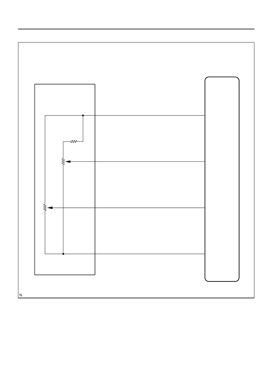
R17
Remote Control Mirror LH
D22
Driver Door ECU
VDD
SV
SH
BR–W
BR–Y
L–B
DVC
VSSR
HSSR
GND
L–R
LE1
9
16
10
15
18
11
12
19
–
DIAGNOSTICS
DRIVER DOOR CONTROL SYSTEM
DI–1811
2005
WIRING DIAGRAM
DI–1812
–
DIAGNOSTICS
DRIVER DOOR CONTROL SYSTEM
2006
INSPECTION PROCEDURE
1
Check remote control mirror position sensor (See page
).
NG
Replace remote control mirror.
OK
2
Check wire harness and connector between remote control mirror position sen-
sor and driver door ECU (See page
NG
Repair or replace harness or connector.
OK
Proceed to next circuit inspection shown in
problem symptoms table (See page
).
–
DIAGNOSTICS
DRIVER DOOR CONTROL SYSTEM
DI–1813
2007
Power window master switch circuit
CIRCUIT DESCRIPTION
The power window master switch circuit can be checked using the DTC check (refer to
).
INSPECTION PROCEDURE
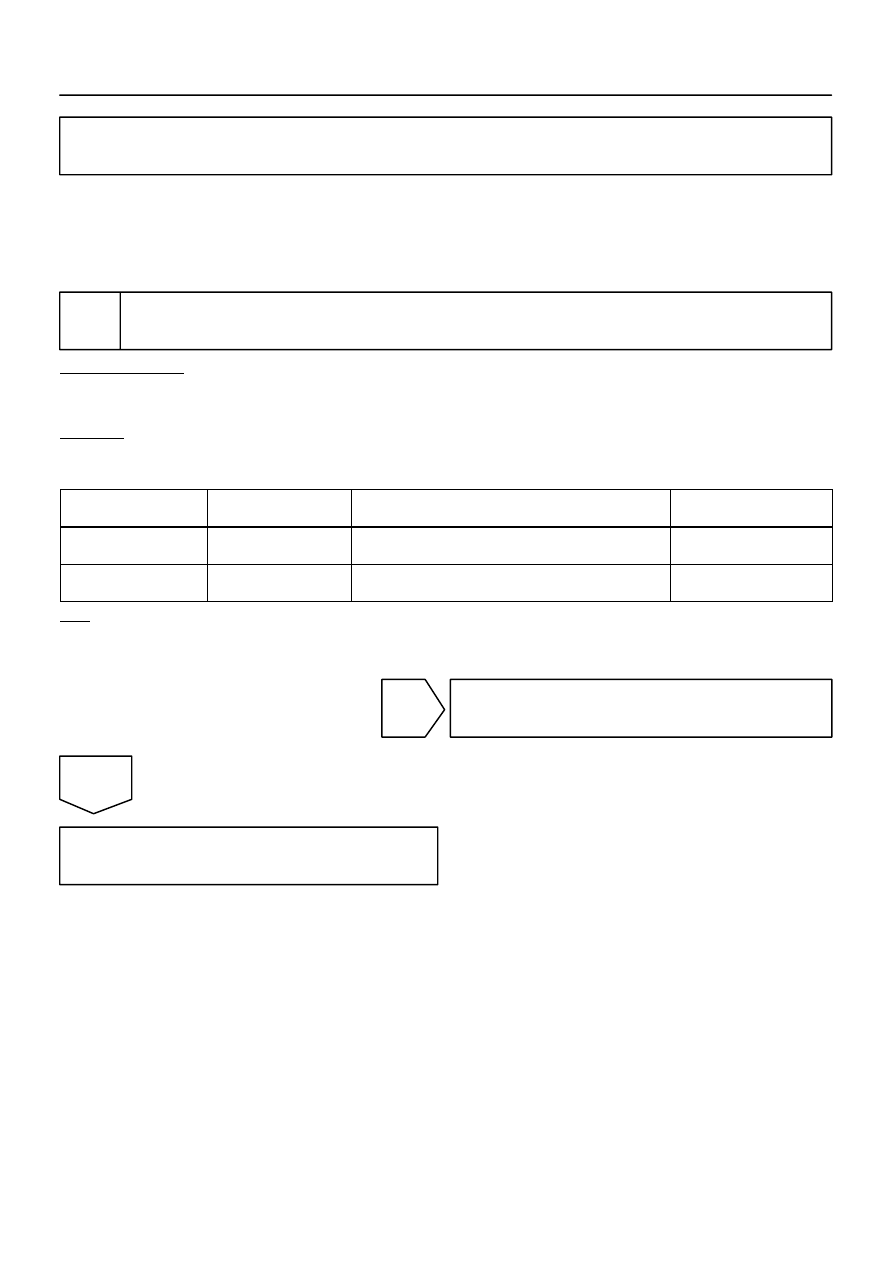
1
Check the power window master switch using hand–held tester.
PREPARATION:
(a)
Connect the hand–held tester to the DLC3.
(b)
Turn the ignition switch ON.
CHECK:
According to the display on the tester, read the DATA LIST.
D–DOOR:
Item
Measurement Item/Dis-
play (Range)
Normal Condition
Diagnostic Note
D P/W AUTO SW
P/W auto SW signal/
ON or OFF
ON: P/W auto UP/DOWN SW is ON
OFF: P/W auto UP/DOWN SW is OFF
–
P P/W AUTO SW
P/W auto SW signal/
ON or OFF
ON: P/W auto UP/DOWN SW is ON
OFF: P/W auto UP/DOWN SW is OFF
–
OK:
Indication on the tester switches between ON and OFF in accordance with the window auto up
operation status.
OK
Proceed to next circuit inspection shown in
problem symptoms table (See page
NG
Replace the driver door ECU.
DI94N–04
DIDER–01
DI–1814
–
DIAGNOSTICS
PASSENGER DOOR CONTROL SYSTEM
2008
PASSENGER DOOR CONTROL SYSTEM
PRECAUTION
NOTICE:
When disconnecting the battery terminal, initialize the following system after the terminal is recon-
nected.
System Name
See Page
Back Door Power Window Control System
Нет комментариевНе стесняйтесь поделиться с нами вашим ценным мнением.
Текст