Toyota Sequoia (2005). Manual — part 215
D11993
(+)
(–)
Shift Solenoid Valve SR:
–
DIAGNOSTICS
AUTOMATIC TRANSMISSION
DI–655
849
3
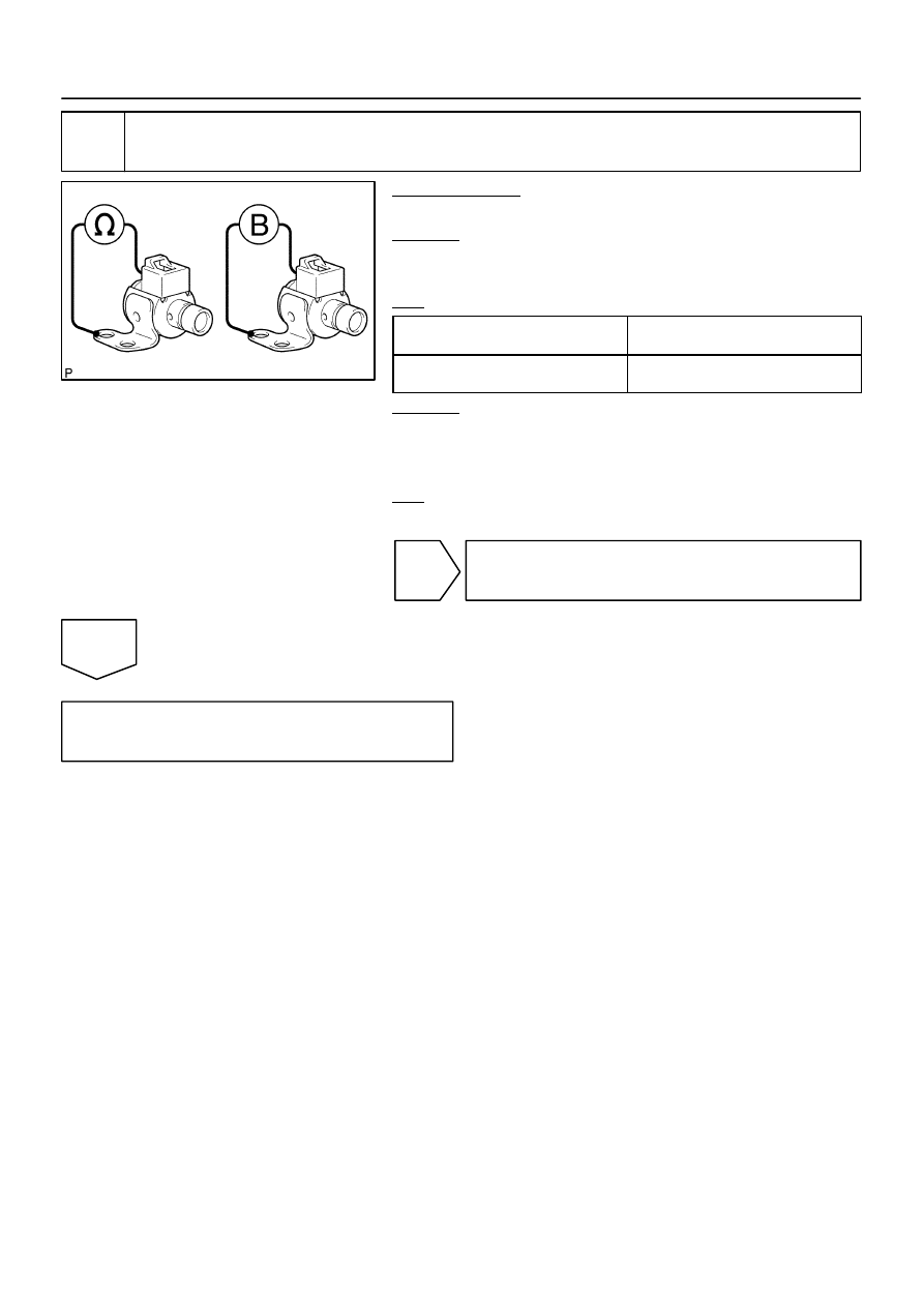
Check shift solenoid valve SR.
PREPARATION:
Remove the shift solenoid valve SR (See page
CHECK:
Measure the resistance according to the value(s) in the table
below.
OK:
Tester Connection
Specified Condition
20
C (68
F)
Solenoid Connector (SR) – Solenoid
Body (SR)
11 to 15
Ω
CHECK:
Connect the battery positive lead to the solenoid connector ter-
minal and the battery negative lead to the solenoid body
ground.
OK:
Solenoid sounds an operation noise.
NG
Replace the shift solenoid valve SR
(See page
OK
Repair or replace the transmission wire
(See page
).
D14171
Line Pressure
Control Pressure
Current Flow to Solenoid
D14172
ON
OFF
1 cycle
D14173
DI–656
–
DIAGNOSTICS
AUTOMATIC TRANSMISSION
850
DTC
P2714
Pressure Control Solenoid ”D” Performance
(Shift Solenoid Valve SLT)
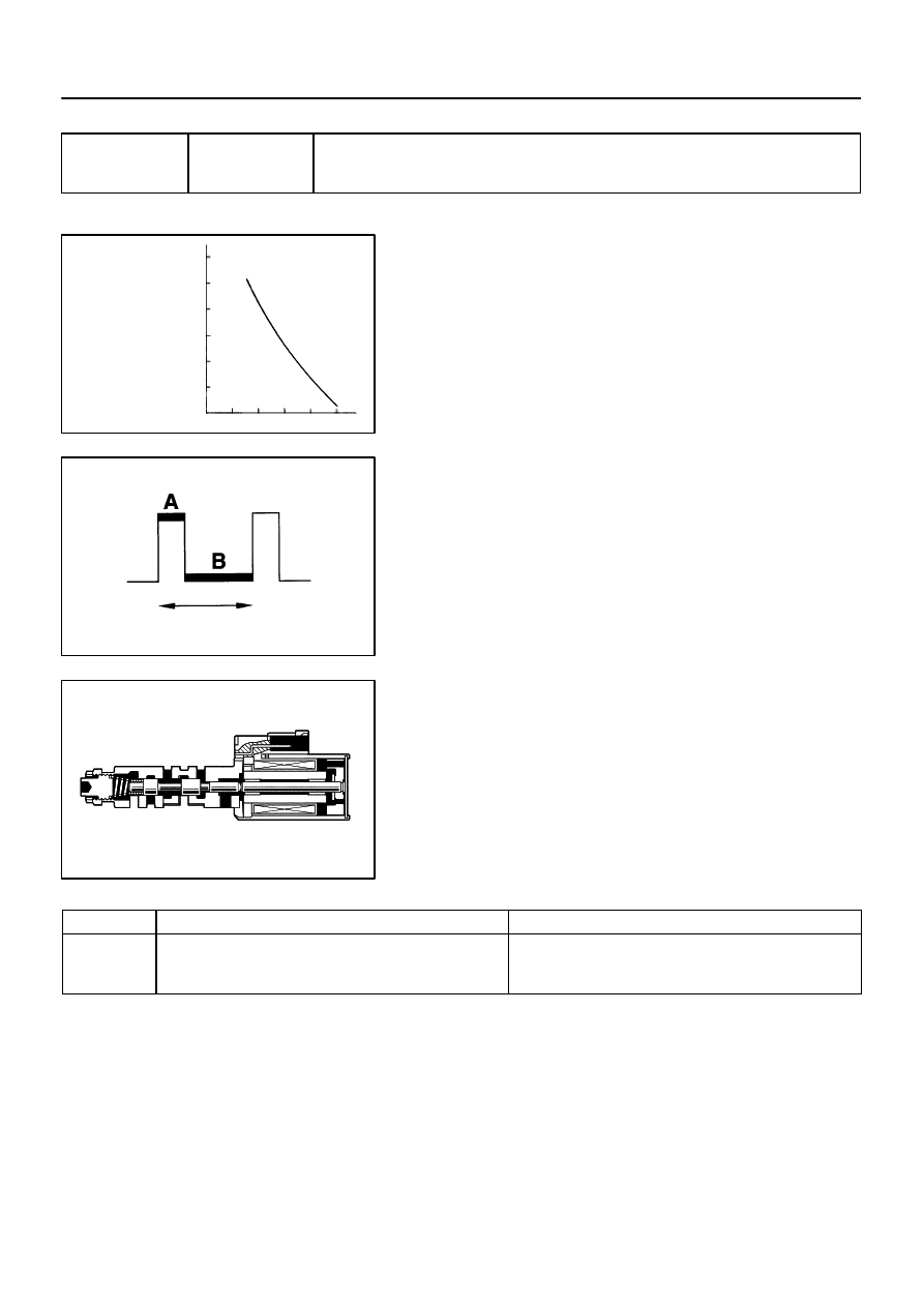
SYSTEM DESCRIPTION
The linear solenoid valve (SLT) controls the transmission line
pressure for smooth transmission operation based on signals
from the throttle position sensor and the vehicle speed sensor.
The ECM adjusts the duty cycle of the SLT solenoid valve to
control hydraulic line pressure coming from the primary regula-
tor valve. Appropriate line pressure assures smooth shifting
with varying engine outputs.
(*): Duty Ratio
The duty ratio is the ratio of the period of continuity in one cycle.
For example, if A is the period of continuity in one cycle, and B
is the period of non–continuity, then
Duty Ratio = A/(A + B) x 100 (%)
DTC No.
DTC Detection Condition
Trouble Area
P2714
ECM detects a malfunction on SLT (ON side) according to the
revolution difference of the turbine and the output shaft, and
also by the oil pressure. (2–trip detection logic)
Shift solenoid valve SLT remains open or closed
Valve body is blocked
Automatic transmission (clutch, brake or gear, etc.)
MONITOR DESCRIPTION
The ECM calculates the amount of heat absorbed by the friction material based on the difference in revolu-
tion (clutch slippage) between the turbine and output shaft. The ECM turns on the MIL and outputs this DTC
when the amount of heat absorption exceeds the specified value.
When the shift solenoid valve SLT remains on, oil pressure goes down and clutch engagement force de-
creases.
NOTE: If you continue driving under these conditions, the clutch will burn out and the vehicle will no longer
be drivable.
DIDJL–01

–
DIAGNOSTICS
AUTOMATIC TRANSMISSION
DI–657
851
MONITOR STRATEGY
Related DTCs
P2714
Shift solenoid valve SLT/ON malfunction
Main
Shift solenoid valve SLT
Required sensors/Components
Sub
Valve body, ATF temperature sensor, Speed sensor (NT), Speed sensor
(NO)
Frequency of operation
Continuous
Duration
Immediate
MIL operation
2 driving cycles
Sequence of operation
None
TYPICAL ENABLING CONDITIONS
It
Specification
Item
Minimum
Maximum
All:
Turbine speed sensor circuit
Not circuit malfunction
Output speed sensor circuit
Not circuit malfunction
Transmission Fluid Temperature Sensor
circuit
Not circuit malfunction
Shift solenoid valve S1 circuit
Not circuit malfunction
Shift solenoid valve S2 circuit
Not circuit malfunction
Shift solenoid valve SR circuit
Not circuit malfunction
Shift solenoid valve SL1 circuit
Not circuit malfunction
Shift solenoid valve SL2 circuit
Not circuit malfunction
Shift solenoid valve SLT circuit
Not circuit malfunction
ECT (Engine coolant temperature) sensor
circuit
Not circuit malfunction
KCS sensor circuit
Not circuit malfunction
ETCS (Electric throttle control system)
Not system down
Transmission range
”D”
ECT
40
°
C (104
°
F) or more
–
Spark advance from Max. retard timing by
KCS control
0
°
CA or more
–
Engine
Starting
Transfer range
”HIGH”
*1
TFT (transmission fluid temperature)
10
°
C or more
–
Transfer range ”HIGH” *1 (This condition is applied only 4WD)
*1 Following conditions met
Vehicle speed sensor circuit
Not circuit malfunction
Output shaft speed sensor circuit
Not circuit malfunction
Transfer output speed
143 rpm or more
–
NO/NOtf (Transfer input speed/Transfer
output speed)
0.9 to 1.1
D14174
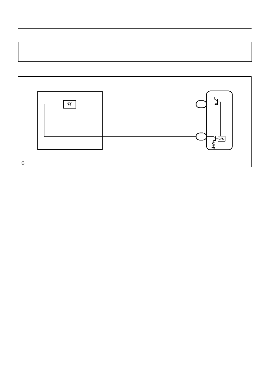
ECM
SLT+
SLT–
E7
13
12
B–R
G–Y
E1 Electronically Controlled
Transmission Solenoid
E7
G
GR
14
6
SLT+
SLT–
+B
DI–658
–
DIAGNOSTICS
AUTOMATIC TRANSMISSION
852
TYPICAL MALFUNCTION THRESHOLDS
Detection criteria
Threshold
Summation of C1 clutch heat generations
=
∑
(Turbine speed – Output speed x Temporary ratio)
Specified value
WIRING DIAGRAM
Нет комментариевНе стесняйтесь поделиться с нами вашим ценным мнением.
Текст