Toyota Sequoia (2005). Manual — part 216

–
DIAGNOSTICS
AUTOMATIC TRANSMISSION
DI–659
853
INSPECTION PROCEDURE
HINT:
Performing the ACTIVE TEST using the hand–held tester allows the relay, VSV, actuator and so on to oper-
ate without parts removal. Performing the ACTIVE TEST as the first step of troubleshooting is one method
to shorten labor time.
It is possible to display the DATA LIST during the ACTIVE TEST.
(a)
Warm up the engine.
(b)
Turn the ignition switch off.
(c)
Connect the hand–held tester to the DLC3.
(d)
Turn the ignition switch to the ON position.
(e)
Turn on the tester.
(f)
Select the item ”DIAGNOSIS / ENHANCED OBD II / ACTIVE TEST”.
(g)
According to the display on tester, perform the ”ACTIVE TEST”.
Item
Test Details
Diagnostic Note
LINE PRESS UP *
[Test Details]
Operate the shift solenoid SLT and raise the line pressure.
[Vehicle Condition]
Vehicle Stopped.
IDL: ON
[HINT]
OFF: Line pressure up (When the active test of ”Control the Line Pres-
sure Up” is performed, the ECM commands the SLT solenoid to turn
off).
ON: No action (normal operation)
–
*: ”LINE PRESS UP” in the ACTIVE TEST is performed to check the line pressure changes by connecting
the SST to the automatic transaxle, which is used in the HYDRAULIC TEST (See page
HINT:
The pressure values in ACTIVE TEST and HYDRAULIC TEST are different from each other.
Normally, the line pressure detected in the ACTIVE TEST is approximately half of the value detected
in the HYDRAULIC TEST’s stall test.

DI–660
–
DIAGNOSTICS
AUTOMATIC TRANSMISSION
854
1
Check other DTCs output (in addition to DTC P2714).
PREPARATION:
(a)
Turn the ignition switch off.
(b)
Connect the OBD II scan tool or hand–held tester to the DLC3.
(c)
Turn the ignition switch to the ON position.
(d)
Turn on the tester.
(e)
Select the item ”DIAGNOSIS / ENHANCED OBD II / DTC INFO / CURRENT CODES”.
CHECK:
Read the DTCs using the OBD II scan tool or the hand–held tester.
RESULT:
Display (DTC output)
Proceed to
Only ”P2714” is output
A
”P2714” and other DTCs
B
HINT:
If any other codes besides ”P2714” are output, perform troubleshooting for those DTCs first.
B
).
A
D11987
2
1
(+)
(–)
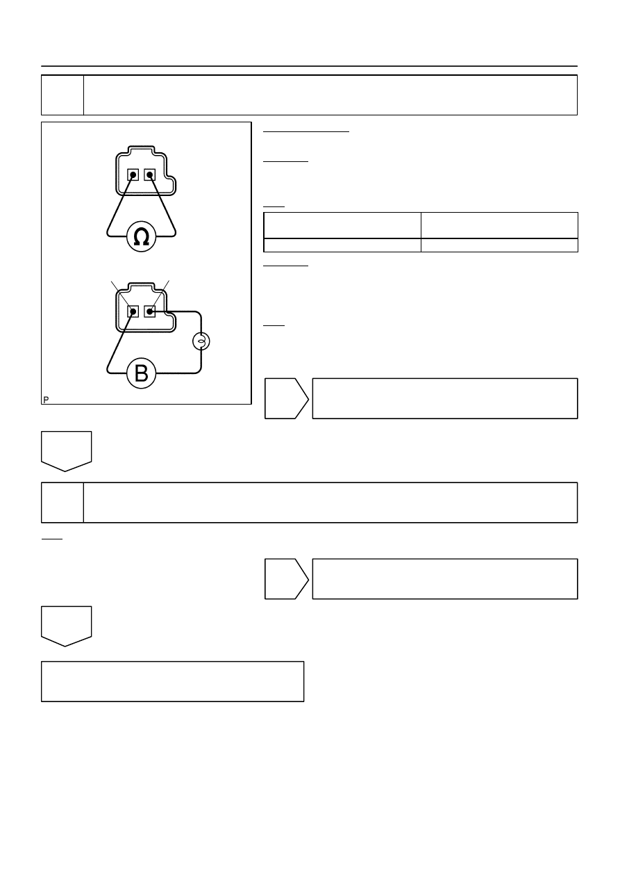
Shift Solenoid Valve SLT:
–
DIAGNOSTICS
AUTOMATIC TRANSMISSION
DI–661
855
2
Inspect shift solenoid valve SLT operation.
PREPARATION:
Remove the shift solenoid valve SLT (See page
CHECK:
Measure the resistance according to the value(s) in the table
below.
OK:
Tester Connection
Specified Condition
20
C (68
F)
1 – 2
5.0 to 5.6
Ω
CHECK:
Connect the positive (+) lead with a 21 W bulb to terminal 2 and
the negative (–) lead to terminal 1 of the solenoid valve connec-
tor, then check the movement of the valve.
OK:
The solenoid makes an operating sound.
NG
Replace the shift solenoid valve SLT
(See page
OK
3
Inspect valve body
OK:
There are no foreign objects on each valve.
NG
Repair or replace valve body.
OK
Repair or replace transmission (See page

DI–662
–
DIAGNOSTICS
AUTOMATIC TRANSMISSION
856
DTC
P2716
Pressure Control Solenoid ”D” Electrical
(Shift Solenoid Valve SLT)
CIRCUIT DESCRIPTION
See page
DTC No.
DTC Detection Condition
Trouble Area
P2716
Open or short is detected in shift solenoid valve SLT circuit for
1 second or more while driving (1–trip detection logic).
Open or short in shift solenoid valve SLT circuit
Shift solenoid valve SLT
ECM
MONITOR DESCRIPTION
When an open or short in the linear solenoid valve (SLT) circuit is detected, the ECM interprets this as a fault.
The ECM will turn on the MIL and store the DTC.
MONITOR STRATEGY
Related DTCs
P2716
Shift solenoid valve SLT/Range check
Required sensors/Components
Shift solenoid valve SLT
Frequency of operation
Continuous
Duration
1 sec.
MIL operation
Immediate
Sequence of operation
None
TYPICAL ENABLING CONDITIONS
It
Specification
Item
Minimum
Maximum
The monitor will run whenever this DTC is
not present.
See page
Solenoid current cut status
Not cut
Battery voltage
11 V or more
–
CPU command duty ratio to SLT
19% or more
–
Ignition switch
ON
Starter
OFF
TYPICAL MALFUNCTION THRESHOLDS
Detection criteria
Threshold
Solenoid status from IC
Fail (Open or short)
COMPONENT OPERATING RANGE
Parameter
Standard value
Output signal duty
Less than 100%
DIDJM–01
Нет комментариевНе стесняйтесь поделиться с нами вашим ценным мнением.
Текст