Toyota Sequoia (2005). Manual — part 199
D14162
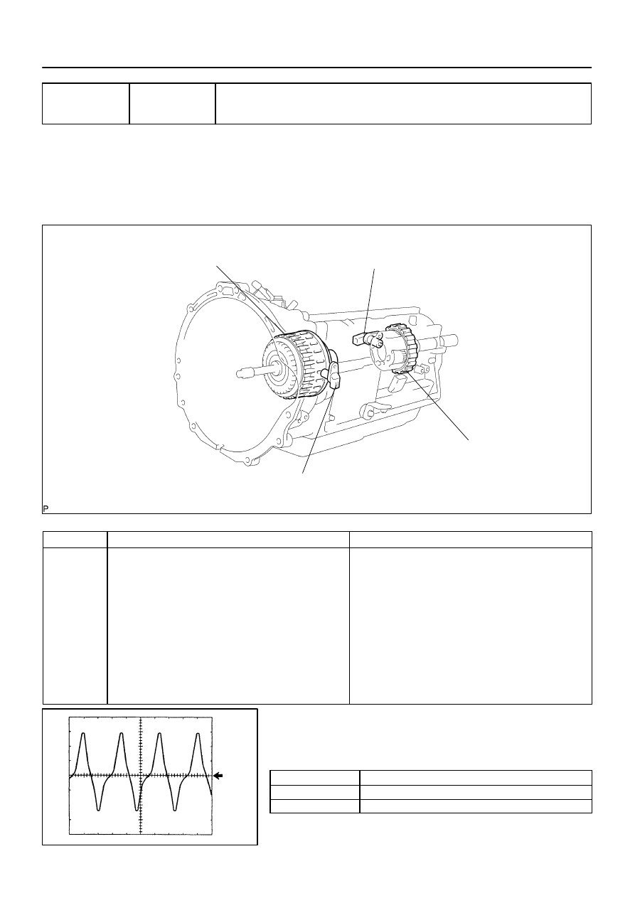
Clutch Drum
(Timing Rotor)
Input Speed Sensor NT
(Transmission Revolution Sensor NT)
Output Speed Sensor SP2
(Transmission Revolution Sensor SP2)
Parking Gear
(Timing Rotor)
D14148
GND
1 V/DIV
2 ms/DIV
–
DIAGNOSTICS
AUTOMATIC TRANSMISSION
DI–591
785
DTC
P0717
Input Speed Sensor Circuit No Signal
CIRCUIT DESCRIPTION
This sensor detects the rotation speed of the turbine which shows the input revolution of transmission. By
comparing the input turbine speed signal (NT) with the counter gear speed sensor signal (SP2), the ECM
detects the shift timing of the gears and appropriately controls the engine torque and hydraulic pressure ac-
cording to various conditions, thus, providing smooth gear shift.
DTC No.
DTC Detection Condition
Trouble Area
P0717
All conditions below are detected for 5 secs. or more
(1–trip detection logic)
(a) Gear change is not performed
(b) Gear position: 4th or 5th
(c) T/M input shaft rpm: 300 rpm or less
(d) T/M output shaft rpm: 1,000 rpm or more
(e) Park/neutral position switch:
NSW input signal is OFF
R input signal is OFF
L input signal is OFF
(f) Shift solenoid valves, park/neutral position switch and ve-
hicle speed sensor are in normal operation
Open or short in speed sensor (NT) circuit
Speed sensor (NT)
ECM
Automatic transmission (clutch, brake or gear, etc.)
Reference (Using an oscilloscope):
Check the waveform between terminals NT+ and NT– of
the ECM connector.
Standard: Refer to the illustration.
Terminal
NT+ – NT–
Tool setting
1V/DIV, 2ms/DIV
Vehicle condition
Engine idle speed (P or N position)
DIDJ8–01

DI–592
–
DIAGNOSTICS
AUTOMATIC TRANSMISSION
786
MONITOR DESCRIPTION
This DTC indicates that pulse is not output from the speed sensor NT (Turbine (input) speed sensor ) or is
output only little. The NT terminal of the ECM detects the revolving signal from the speed sensor (NT) (input
RPM). The ECM outputs a gearshift signal comparing the
input speed sensor (NT) with the output speed
sensor (SP2).
While the vehicle is operating in the 4th or 5th gear position in the shift position of D, if the input shaft revolu-
tion is less than 300 rpm
*1
although the output shaft revolution is more than 1000 rpm or more
*2
, the ECM
detects the trouble, illuminates the MIL and stores the DTC.
*1: Pulse is not output or is irregularly output.
*2: The vehicle speed is approx. 50 km/h (31 mph) or more.
MONITOR STRATEGY
Related DTCs
P0717
Speed sensor (NT)/Verify pulse input
R
i d
/C
t
Main
Speed sensor (NT)
Required sensors/Components
Sub
Speed sensor (NO)
Frequency of operation
Continuous
Duration
5 sec.
MIL operation
Immediate
Sequence of operation
None
TYPICAL ENABLING CONDITIONS
It
Specification
Item
Minimum
Maximum
The monitor will run whenever this DTC is
not present.
See page
Shift change
Shift change is completed and before starting next shift change operation
ECM selected gear
4th or 5th
Output shaft rpm
1,000 rpm or more
–
NSW switch
OFF
R switch
OFF
L switch
OFF
Engine
Running
Ignition switch
ON
Starter
OFF
TYPICAL MALFUNCTION THRESHOLDS
Detection criteria
Threshold
Sensor signal rpm
Less than 300 rpm
COMPONENT OPERATING RANGE
Parameter
Standard value
Speed sensor (NT)
Input speed is equal to engine speed when lock–up ON.
D14163
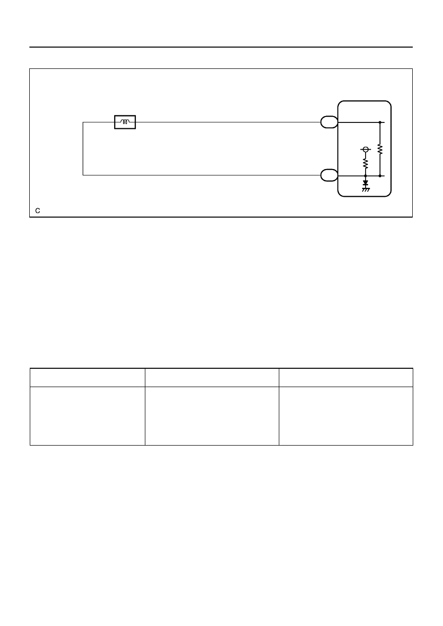
ECM
NT+
NT–
35
W
B
1
2
E7
E7
O1
O/D Direct Clutch Speed Sensor
(Input Speed Sensor NT)
E1
27
–
DIAGNOSTICS
AUTOMATIC TRANSMISSION
DI–593
787
WIRING DIAGRAM
INSPECTION PROCEDURE
HINT:
According to the DATA LIST displayed by the OBD II scan tool or hand–held tester, you can read the value
of the switch, sensor, actuator and so on without parts removal. Reading the DATA LIST as the first step of
troubleshooting is one method to shorten labor time.
(a)
Warm up the engine.
(b)
Turn the ignition switch off.
(c)
Connect the OBD II scan tool or hand–held tester to the DLC3.
(d)
Turn the ignition switch to the ON position.
(e)
Push the ”ON” button of the OBD II scan tool or the hand–held tester.
(f)
When you use the hand–held tester:
Select the item ”DIAGNOSIS / ENHANCED OBD II / DATA LIST”.
(g)
According to the display on the tester, read the ”DATA LIST”.
Item
Measurement Item/
Range (display)
Normal Condition
SPD (NT)
Input Turbine Speed/
display: 50 r/min
[HINT]
Lock–up ON (After warming up the engine);
Input Turbine speed (NT) equal to the engine
speed.
Lock–up OFF (Idling at N position);
Input Turbine speed (NT) nearly equal to the en-
gine speed.
HINT:
SPD (NT) is always 0 while driving:
Open or short in the sensor or circuit.
SPD (NT) is always more than 0 and less than 300 rpm while driving the vehicle at 50 km/h (31 mph)
or more:
Sensor trouble, improper installation, or intermittent connection trouble of the circuit.
D14164
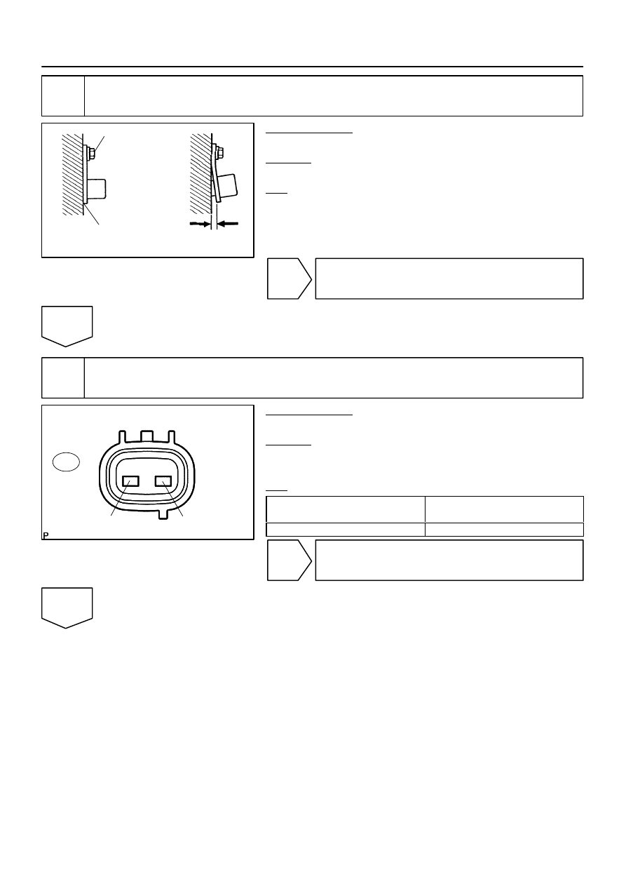
OK
NG
5.4 N·m
(55 kgf·cm, 48 in.·lbf)
No Clearance
D14165
Sensor Side:
(Connector Front View):
2
1
O1
DI–594
–
DIAGNOSTICS
AUTOMATIC TRANSMISSION
788
1
Inspect speed sensor installation.
PREPARATION:
Jack up the vehicle.
CHECK:
Check the speed sensor (NT) installation.
OK:
The installation bolt is tightened properly and there is
no clearance between the sensor and transmission
case.
Torque: 5.4 N·m (55 kgf·cm, 48 in.·lbf)
NG
Replace speed sensor NT (See page
).
OK
2
Inspect speed sensor NT.
PREPARATION:
Disconnect the speed sensor connector from the transmission.
CHECK:
Measure the resistance according to the value(s) in the table
below.
OK:
Tester Connection
Specified Condition
20
C (68
F)
1 – 2
560 to 680
Ω
NG
Replace speed sensor NT (See page
).
OK
Нет комментариевНе стесняйтесь поделиться с нами вашим ценным мнением.
Текст