Toyota Sequoia (2005). Manual — part 198
D14161
E8
E7
E6
E5
E4
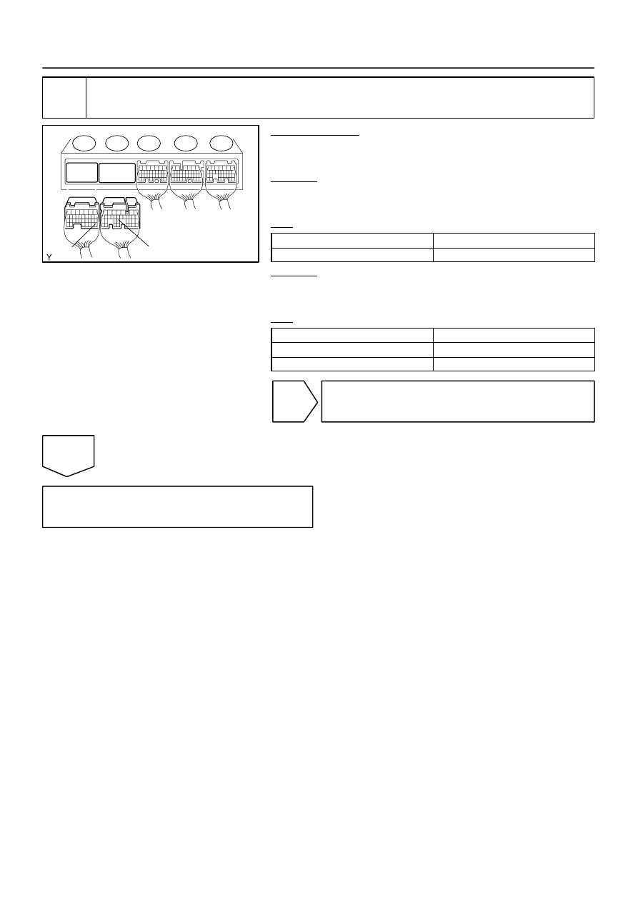
ECM:
THO1
E2
–
DIAGNOSTICS
AUTOMATIC TRANSMISSION
DI–587
781
2
Check harness and connector (Transmission wire – ECM).
PREPARATION:
(a)
Connect the transmission wire connector.
(b)
Disconnect the connector of the ECM.
CHECK:
Measure the resistance according to the value(s) in the table
below.
OK:
Tester Connection
Specified Condition
E7 – 24 (THO1) – E8 – 28 (E2)
79
Ω
to 156 k
Ω
CHECK:
Measure the resistance according to the value(s) in the table
below.
OK:
Tester Connection
Specified Condition
E7 – 24 (THO1) – Body ground
10 k
Ω
or higher
E8 – 28 (E2) – Body ground
↑
NG
Repair or replace the harness or connector
(See page
).
OK
Replace the ECM (See page

DI–588
–
DIAGNOSTICS
AUTOMATIC TRANSMISSION
782
DTC
P0711
Transmission Fluid Temperature Sensor ”A”
Performance
CIRCUIT DESCRIPTION
See page
DTC No.
DTC Detection Condition
Trouble Area
P0711
Both (a) and (b) are detected: (2–trip detection logic)
(a) Intake air and engine coolant temps. are more than –20
°
C
(–4
F) at engine start
(b) After normal driving for over 22 min. and 9 km (6 mile) or
more, ATF temp. is less than 10
°
C (50
F)
Transmission wire (ATF temperature sensor No.1)
MONITOR DESCRIPTION
This DTC indicates that there is a problem with output from the automatic transmission fluid (ATF) tempera-
ture sensor and that the sensor itself is defective. The ATF temperature sensor converts the ATF tempera-
ture to an electrical resistance value. Based on the resistance, the ECM determines the ATF temperature
and detects an open or short in the ATF temperature circuit or a fault in the ATF temperature sensor.
After running the vehicle for a certain period, the ATF temperature should increase. If the ATF temperature
is below 20
C (68
F) after running the vehicle for a certain period, the ECM interprets this as a fault, and
turns on the MIL.
MONITOR STRATEGY
Related DTCs
P0711
ATF temperature sensor/Rationality check
Required sensors/Components
ATF temperature sensor (TFT sensor)
Frequency of operation
Continuous
Duration
3 sec.
MIL operation
2 driving cycles
Sequence of operation
None
TYPICAL ENABLING CONDITIONS
It
Specification
Item
Minimum
Maximum
The monitor will run whenever this DTC is
not present.
See page
TFT (transmission fluid temperature) sen-
sor circuit
Not circuit malfunction
ECT (Engine coolant temperature) sensor
circuit
Not circuit malfunction
IAT (Intake air temperature) sensor circuit
Not circuit malfunction
Time after engine start
21 min.
and 40 sec.
Driving distance after engine start
9 km (5.6 mile) or more
–
IAT (12 sec. after engine start)
–10
°
C (14
°
F) or more
–
ECT (12 sec. after engine start)
–10
°
C (14
°
F) or more
–
DIDJ7–01

–
DIAGNOSTICS
AUTOMATIC TRANSMISSION
DI–589
783
TYPICAL MALFUNCTION THRESHOLDS
Detection criteria
Threshold
TFT (transmission fluid temperature)
Less than 20
°
C (68
°
F)
(varies with TFT (transmission fluid temperature) at engine start)
WIRING DIAGRAM
See page
INSPECTION PROCEDURE
HINT:
According to the DATA LIST displayed by the OBD II scan tool or hand–held tester, you can read the value
of the switch, sensor, actuator and so on without parts removal. Reading the DATA LIST as the first step of
troubleshooting is one method to shorten labor time.
(a)
Warm up the engine.
(b)
Turn the ignition switch off.
(c)
Connect the OBD II scan tool or hand–held tester to the DLC3.
(d)
Turn the ignition switch to the ON position.
(e)
Push the ”ON” button of the OBD II scan tool or the hand–held tester.
(f)
When you use the hand–held tester:
Select the item ”DIAGNOSIS / ENHANCED OBD II / DATA LIST”.
(g)
According to the display on the tester, read the ”DATA LIST”.
Item
Measurement Item/
Range (display)
Normal Condition
AT FLUID TEMP 1
ATF Temp. Sensor Value/
min.: –40
C (–40
F)
max.: 215
C (419
F)
After Stall Test;
Approx. 80
C (176
F)
Equal to ambient temperature when cold soak
HINT:
When DTC P0712 is output and hand–held tester output is 150
C (302
F) or more, there is a short circuit.
When DTC P0713 is output and hand–held tester output is –40
C (–40
F), there is an open circuit.
Measure the resistance between terminal THO1 (OT) and body ground.
Temperature Displayed
Malfunction
–40
°
C (–40
°
F)
Open circuit
150
°
C (302
°
F) or more
Short circuit
HINT:
If a circuit related to the ATF temperature sensor becomes open, P0713 is immediately set (in 0.5 second).
When P0713 is set, P0711 cannot be detected.
It is not necessary to inspect the circuit when P0711 is set.
DI–590
–
DIAGNOSTICS
AUTOMATIC TRANSMISSION
784
1
Check other DTCs output (in addition to DTC P0711).
PREPARATION:
(a)
Turn the ignition switch off.
(b)
Connect the OBD II scan tool or hand–held tester to the DLC3.
(c)
Turn the ignition switch to the ON position.
(d)
Turn on the tester.
(e)
Select the item ”DIAGNOSIS / ENHANCED OBD II / DTC INFO / CURRENT CODES”.
CHECK:
Read the DTCs using the OBD II scan tool or the hand–held tester.
RESULT:
Display (DTC output)
Proceed to
Only ”P0711” is output
A
”P0711” and other DTCs
B
HINT:
If any other codes besides ”P0711” are output, perform troubleshooting for those DTCs first.
B
).
A
2
Check transmission fluid level (See page
).
OK:
Automatic transmission fluid level is correct.
NG
Add fluid
.
OK
Replace the transmission wire (ATF tempera-
ture sensor) (See page
Нет комментариевНе стесняйтесь поделиться с нами вашим ценным мнением.
Текст