Toyota Sequoia (2005). Manual — part 299
F14403
F16959
A9
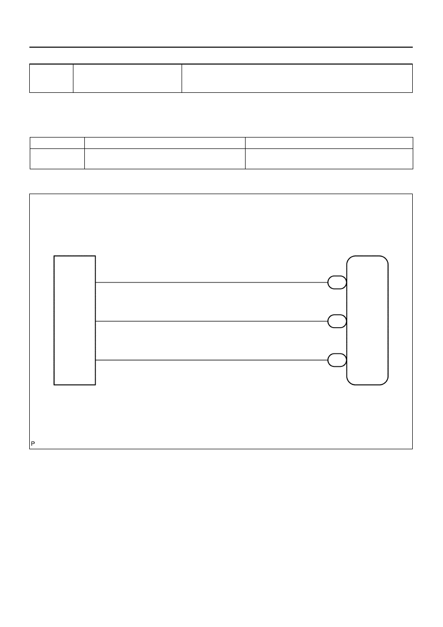
Booster Pedal
Force Switch
(ACTIVE Brake Booster)
ABS & VSC Actuator
(Skid Control ECU)
STS
PSNC
PSNO
5
BR–Y
V–W
R–Y
20
S1
18
21
S1
S1
2
1
STS
PSNC
PSNO
–
DIAGNOSTICS
ABS WITH EBD & BA & TRAC & VSC SYSTEM
DI–991
1185
DTC
C1363 / 63
Malfunction in Booster Pedal Force
Switch
CIRCUIT DESCRIPTION
Detects if the brake pedal is depressed.
DTC No.
DTC Detecting Condition
Trouble Area
C1363 / 63
Signal transmitted from booster pedal force switch to ECU
is abnormal.
Booster pedal force switch (Active brake booster)
Booster pedal force switch (Active brake booster) circuit
WIRING DIAGRAM
DIDMF–01
F19145
Yaw Rate
(Deceleration)
Sensor
STS
DI–992
–
DIAGNOSTICS
ABS WITH EBD & BA & TRAC & VSC SYSTEM
1186
INSPECTION PROCEDURE
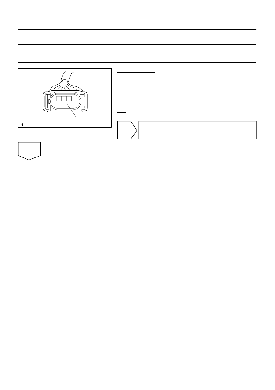
1
Check voltage between terminal STS of brake pedal force switch and body
ground.
PREPARATION:
Disconnect the brake pedal force switch connector.
CHECK:
(a)
Turn the ignition switch to the ON position.
(b)
Measure the voltage between STS of brake pedal force
switch harness side connector and body ground.
OK:
Voltage: About 6 V
NG
Go to step 3.
OK
F13989
1
2
(Oscilloscope)
5
(Oscilloscope)
ON
F17283
(Reference)
IG ON Released
Depressed
0 V
6 V
0 V
6 V
PSNC–STS
PSNO–STS
F13990
5
2
1
ON
–
DIAGNOSTICS
ABS WITH EBD & BA & TRAC & VSC SYSTEM
DI–993
1187
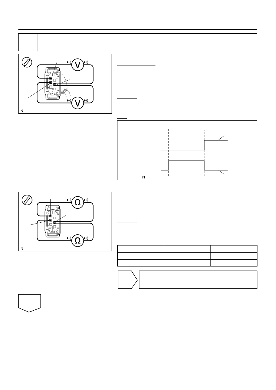
2
Check booster pedal force switch.
When using the oscilloscope:
PREPARATION:
(a)
Connect the oscilloscope between terminals PSNO(1)
and STS(5), PSNC(2) and STS(5) of the brake booster
with connector being connected.
(b)
Turn the ignition switch to the ON position.
CHECK:
Check the signal waveform while the brake pedal is depressed
and released.
OK:
When not using the oscilloscope:
PREPARATION:
(a)
Disconnect the connector from the brake booster.
(b)
Turn the ignition switch to the ON position.
CHECK:
Check continuity between the terminals while depressing and
releasing the brake pedal.
OK:
Tester Connection
Condition
Specified Condition
Terminals 2 – 5
Released
Continuity
Terminals 1 – 5
Depressed
Continuity
NG
Replace brake booster
(See page
OK

DI–994
–
DIAGNOSTICS
ABS WITH EBD & BA & TRAC & VSC SYSTEM
1188
3
Check for open and short circuit in harness and connector between booster ped-
al force switch and skid control ECU (See page
).
NG
Repair or replace harness or connector.
OK
Replace skid control ECU
(See page
).
NOTICE:
When replacing the skid control ECU, perform the zero point calibration (See page
).
Нет комментариевНе стесняйтесь поделиться с нами вашим ценным мнением.
Текст