Toyota Sequoia (2005). Manual — part 297
F16958
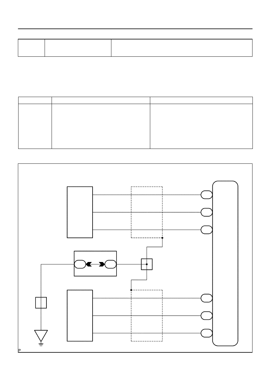
ABS & VSC Actuator
(Skid Control ECU )
M2
Master Cylinder Pressure
Sensor No. 1
VCM
PMC
E1
30
28
29
S1
26
25
27
S1
S1
S1
S1
S1
VCM2
PMC2
E2
B
R
W
3
2
1
VCM
PMC
E1
M3
Master Cylinder Pressure
Sensor No. 2
3
2
1
VCM2
PMC2
E2
B
R
W
(Shielded)
(Shielded)
J28
J/C
A
A
A
A
W–B
Instrument Panel J/B
W–B
J8
J/C
IE
1F
1K
9
12
BR
BR
–
DIAGNOSTICS
ABS WITH EBD & BA & TRAC & VSC SYSTEM
DI–983
1177
DTC
C1360 / 61
Malfunction in Master Cylinder Pres-
sure Sensor
CIRCUIT DESCRIPTION
The master cylinder pressure sensors are connected to the skid control ECU.
Attached to the master cylinder: one reads front master cylinder pressure and the other reads rear master
cylinder pressure.
DTC No.
DTC Detecting Condition
Trouble Area
C1360 / 61
When any of the following conditions are detected:
1. Noise to ECU terminal PMC occurs.
2. While ECU terminal STP is OFF, ECU terminal PMC
voltage is out of standard range.
3. When ECU terminal IG1 voltage is proper, ECU terminal
VCM voltage is out of range.
4. When ECU terminal VCM voltage is proper, ECU termi-
nal PMC voltage is out of range.
Master cylinder pressure sensor
Master cylinder pressure sensor circuit
WIRING DIAGRAM
DI93V–05

DI–984
–
DIAGNOSTICS
ABS WITH EBD & BA & TRAC & VSC SYSTEM
1178
INSPECTION PROCEDURE
1
Is pedal lowered or spongy?
YES
Bleed air from the system (See page
NO
2
Check output value of the master cylinder pressure sensor No. 1 and No. 2.
PREPARATION:
(a)
Connect the hand–held tester to the DLC3.
(b)
Turn the ignition switch to the ON position, and push the hand–held tester main switch ON.
(c)
Select DATA LIST mode on the hand–held tester.
CHECK:
Check that the brake fluid pressure value of the master cylinder pressure sensor displayed on the hand–held
tester changes when depressing the brake pedal.
Item
Measurement Item /
Range (Display)
Normal Condition
Diagnostic Note
MAS CYL PRS 1
Master cylinder pressure
sensor 1 reading / min.: 0
V, max.: 5 V
When brake pedal is re-
leased : 0.3 to 0.9 V
Reading increases when
brake pedal is depressed
MAS CYL PRS 2
Master cylinder pressure
sensor 1 reading / min.: 0
V, max.: 5 V
When brake pedal is re-
leased : 0.3 to 0.9 V
Reading increases when
brake pedal is depressed
OK:
Brake fluid pressure value changes.
OK
Go to step 4.
NG
3
Check for open and short circuit in harness and connector between master cyl-
inder pressure sensor and skid control ECU (See page
NG
Repair or replace harness or connector.
OK

–
DIAGNOSTICS
ABS WITH EBD & BA & TRAC & VSC SYSTEM
DI–985
1179
4
Replace master cylinder pressure sensor and check DTC once more.
PREPARATION:
(a)
Replace the master cylinder pressure sensor (See page
).
(b)
(c)
Turn the ignition switch OFF.
CHECK:
Turn the ignition switch to the ON position, and check if the same DTC is stored in the memory.
RESULT:
DTC is output
A
DTC is not output
B
B
END
A
Replace skid control ECU
(See page
).
NOTICE:
When replacing the skid control ECU, perform the zero point calibration (See page
).

DI–986
–
DIAGNOSTICS
ABS WITH EBD & BA & TRAC & VSC SYSTEM
1180
DTC
C1361 / 62
Abnormal Battery Voltage of VSC Sen-
sor
CIRCUIT DESCRIPTION
Supplies power to the VSC sensors (yaw rate and master cylinder pressure sensors) through terminal IG1.
DTC No.
DTC Detecting Condition
Trouble Area
C1361/62
Voltage from VSC sensor system to ECU is abnormal.
Battery
Charging system
Power source circuit
Skid control ECU
Yaw rate (deceleration) sensor
Master cylinder pressure sensor
DIDME–01
Нет комментариевНе стесняйтесь поделиться с нами вашим ценным мнением.
Текст