Toyota Sequoia (2005). Manual — part 744
TR0DH–01
F19276
F19277
F19278
F19279
–
TRANSFER
REAR OUTPUT SHAFT
TR–27
2965
DISASSEMBLY
1.
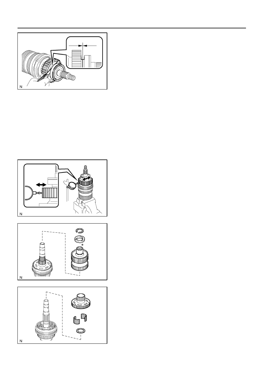
INSPECT DRIVE SPROCKET THRUST CLEARANCE
Using a feeler gauge, measure the thrust clearance of the drive
sprocket.
Standard clearance:
0.15 to 0.24 mm (0.0059 to 0.0094 in.)
Maximum clearance:
0.24 mm (0.0094 in.)
If the clearance exceeds the maximum, replace the drive
sprocket.
2.
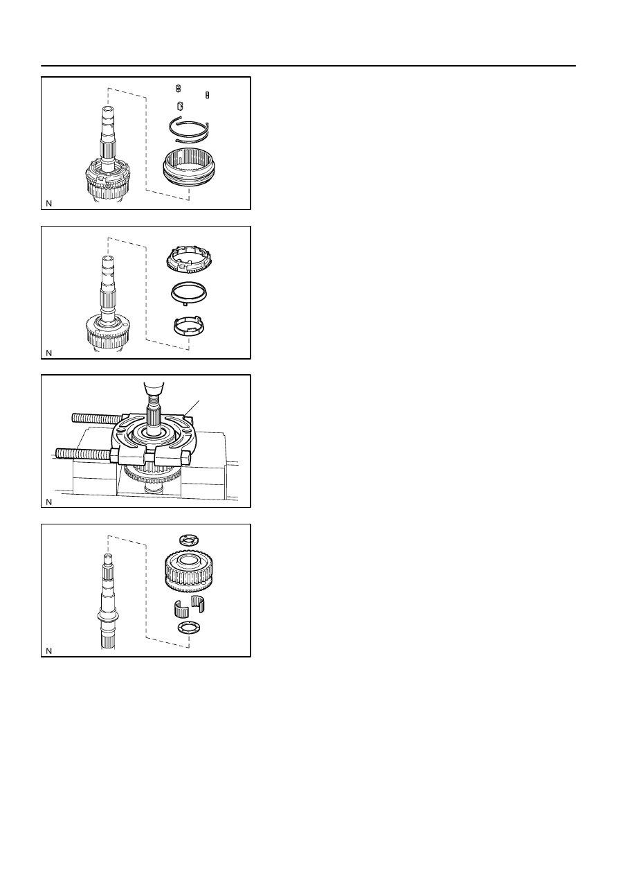
INSPECT DRIVE SPROCKET RADIAL CLEARANCE
Using a dial indicator, measure the radial clearance of the drive
sprocket.
Standard clearance:
0.01 to 0.06 mm (0.0004 to 0.0024 in.)
Maximum clearance:
0.06 mm (0.0024 in.)
If the clearance exceeds the maximum, replace the drive
sprocket, output shaft rear or needle roller bearing.
3.
REMOVE CENTER DIFFERENTIAL CASE
(a)
Using a snap ring expander, remove the snap ring.
(b)
Remove the output shaft spacer No. 2 and ball.
(c)
Remove the center differential case.
4.
REMOVE CLUTCH HUB
Remove the clutch hub, output shaft front needle roller bearing
and output shaft plate washer.
F19280
F19281
F19282
SST
F19283
TR–28
–
TRANSFER
REAR OUTPUT SHAFT
2966
5.
REMOVE FRONT DRIVE CLUTCH SLEEVE
(a)
Using a screwdriver, remove the 2 shifting key springs.
(b)
Remove the 3 shifting keys.
(c)
Remove the front drive clutch sleeve.
6.
REMOVE SYNCHRONIZER RING SET
7.
REMOVE DRIVE SPROCKET
(a)
Using SST and a press, remove the output shaft rear ra-
dial ball bearing.
SST
09555–55010
(b)
Remove the output shaft spacer No. 1 and drive sprocket.
(c)
Remove the output shaft plate washer and drive sprocket
bearing.
TR0DI–01
F19284
A
B
C
D
F19286
–
TRANSFER
REAR OUTPUT SHAFT
TR–29
2967
INSPECTION
1.
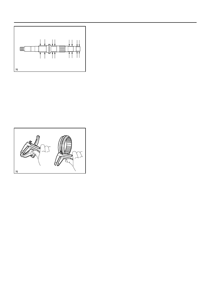
INSPECT OUTPUT SHAFT REAR
Using a micrometer, measure the outer diameter of the output
shaft rear journal surface.
Standard diameter:
Part A: 27.98 to 27.99 mm (1.1016 to 1.1020 in.)
Part B: 31.98 to 32.00 mm (1.2591 to 1.2598 in.)
Part C: 34.98 to 35.00 mm (1.3772 to 1.3780 in.)
Part D: 36.98 to 37.00 mm (1.4559 to 1.4567 in.)
Minimum diameter:
Part A: 27.98 mm (1.1016 in.)
Part B: 31.98 mm (1.2591 in.)
Part C: 34.98 mm (1.3772 in.)
Part D: 36.98 mm (1.4559 in.)
If the outer diameter is less than the minimum, replace the out-
put shaft rear.
2.
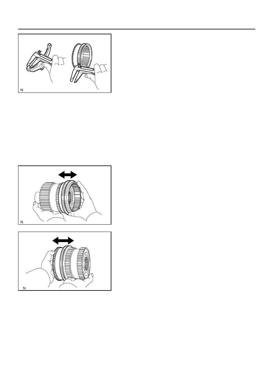
INSPECT FRONT DRIVE CLUTCH SLEEVE AND
GEAR SHIFT FORK NO. 1 CLEARANCE
(a)
Using vernier calipers, measure the thickness of the gear
shift fork No. 1 claw.
Thickness: 10 mm (0.3937 in.)
(b)
Using vernier calipers, measure the width of the groove
of the front drive clutch sleeve.
Width: 10.5 mm (0.4134 in.)
(c)
Calculate the clearance between the front drive clutch
sleeve and gear shift fork No. 1.
Standard clearance:
0.26 to 0.84 mm (0.0102 to 0.0331 in.)
Maximum clearance:
0.84 mm (0.0331 in.)
If the clearance exceeds the maximum, replace the front drive
clutch sleeve or gear shift fork No. 1.
F19285
F19288
F19287
TR–30
–
TRANSFER
REAR OUTPUT SHAFT
2968
3.
INSPECT HIGH AND LOW CLUTCH SLEEVE AND
GEAR SHIFT FORK NO. 2 CLEARANCE
(a)
Using vernier calipers, measure the thickness of the gear
shift fork No. 2 claw.
Thickness: 10 mm (0.3937 in.)
(b)
Using vernier calipers, measure the width of the groove
of the high and low clutch sleeve.
Width: 10.5 mm (0.4134 in.)
(c)
Calculate the clearance between the high and low clutch
sleeve and gear shift fork No. 1.
Standard clearance:
0.26 to 0.84 mm (0.0102 to 0.0331 in.)
Maximum clearance:
0.84 mm (0.0331 in.)
If the clearance exceeds the maximum, replace the high and
low clutch sleeve or gear shift fork No. 2.
4.
INSPECT CENTER DIFFERENTIAL CASE AND FRONT
DRIVE CLUTCH SLEEVE
(a)
Check that the tip of the spline gear of the front drive
clutch sleeve is not worn.
(b)
Install the front drive clutch sleeve to the center differen-
tial case and check that the front drive clutch sleeve
moves smoothly.
5.
INSPECT CENTER DIFFERENTIAL CASE AND HIGH
AND LOW CLUTCH SLEEVE
(a)
Check that the tip of the spline gear of the front drive
clutch sleeve is not worn.
(b)
Install the front drive clutch sleeve to the center differen-
tial case and check that the front drive clutch sleeve
moves smoothly.
Нет комментариевНе стесняйтесь поделиться с нами вашим ценным мнением.
Текст