Toyota Sequoia (2005). Manual — part 745
TR0DJ–01
F19283
F19751
SST
Groove
F19281
F19293
F19294
–
TRANSFER
REAR OUTPUT SHAFT
TR–31
2969
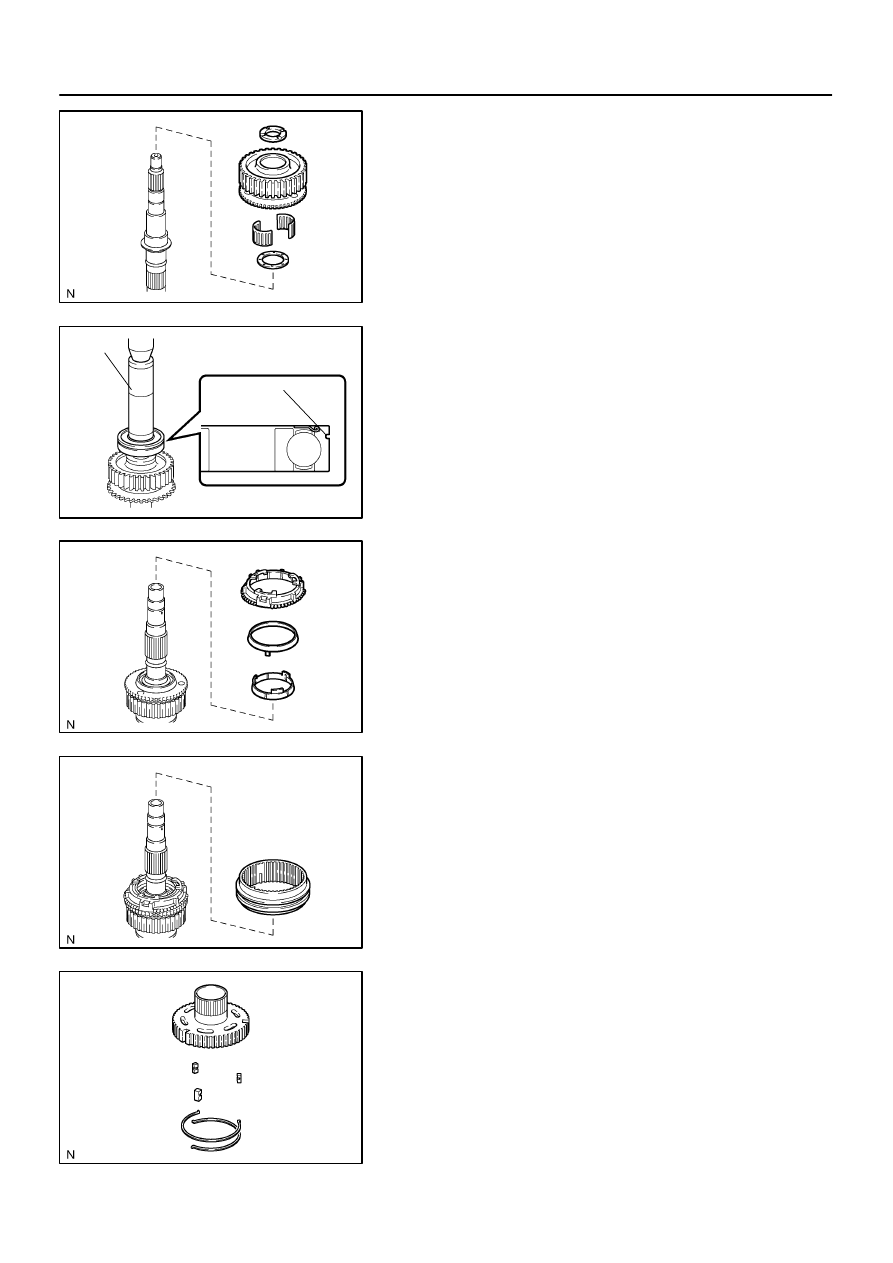
REASSEMBLY
1.
INSTALL DRIVE SPROCKET
(a)
Install the output shaft plate washer and drive sprocket
bearing to the output shaft rear.
(b)
Install the drive sprocket and output shaft spacer No. 1 to
the output shaft rear.
(c)
Using SST and a press, install a new output shaft rear ra-
dial ball bearing.
SST
09316–60011 (09316–00011, 09316–00071)
NOTICE:
Install the output shaft rear radial ball bearing so that the
groove for the snap ring does not face the drive sprocket.
2.
INSTALL SYNCHRONIZER RING SET
3.
INSTALL FRONT DRIVE CLUTCH SLEEVE
4.
INSTALL CLUTCH HUB
(a)
Install the 3 shifting keys to the clutch hub.
(b)
Install the 2 shifting key springs to the clutch hub.
NOTICE:
Position the shifting key springs so that their end gaps are
not aligned.
F19279
F19278
F19276
F19277
TR–32
–
TRANSFER
REAR OUTPUT SHAFT
2970
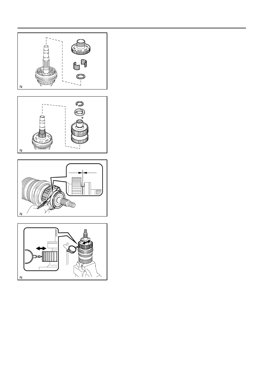
(c)
Install the output shaft plate washer and output shaft front
needle roller bearing to the output shaft rear.
(d)
Install the clutch hub to the output shaft rear.
5.
INSTALL CENTER DIFFERENTIAL CASE
(a)
Install the center differential case to the output shaft rear.
(b)
Install the ball and output shaft spacer No. 2 to the center
differential case.
(c)
Using a snap ring expander, install the snap ring.
6.
INSPECT DRIVE SPROCKET THRUST CLEARANCE
Using a feeler gauge, measure the thrust clearance of the drive
sprocket.
Standard clearance:
0.15 to 0.24 mm (0.0059 to 0.0094 in.)
Maximum clearance:
0.24 mm (0.0094 in.)
If the clearance exceeds the maximum, replace the drive
sprocket.
7.
INSPECT DRIVE SPROCKET RADIAL CLEARANCE
Using a dial indicator, measure the radial clearance of the drive
sprocket.
Standard clearance:
0.01 to 0.06 mm (0.0004 to 0.0024 in.)
Maximum clearance:
0.06 mm (0.0024 in.)
If the clearance exceeds the maximum, replace the drive
sprocket, output shaft rear or needle roller bearing.
TR04O–04
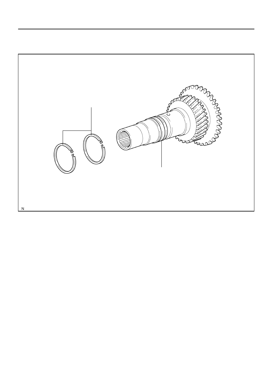
F19233
Oil Seal Ring
Input Shaft
Non–reusable part
–
TRANSFER
INPUT SHAFT
TR–33
2971
INPUT SHAFT
COMPONENTS
TR0DK–01
F19268
F19269
F19270
F19298
TR–34
–
TRANSFER
INPUT SHAFT
2972
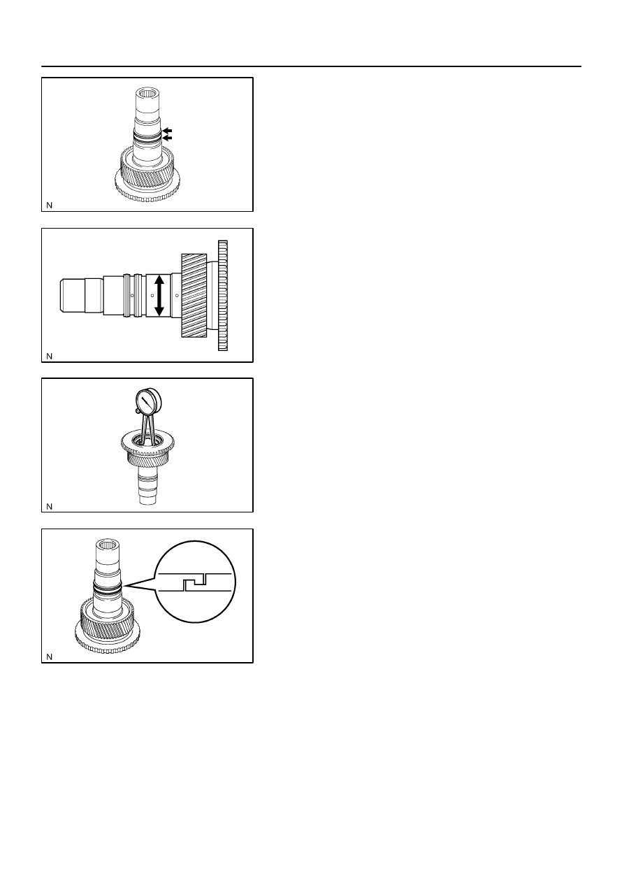
INSPECTION
1.
REMOVE 2 OIL SEAL RINGS
2.
INSPECT INPUT SHAFT
(a)
Using a micrometer, measure the outer diameter of the in-
put shaft journal surface.
Minimum diameter: 47.59 mm (1.8736 in.)
If the outer diameter is less than the minimum, replace the input
shaft.
(b)
Using a dial indicator, measure the inside diameter of the
input shaft bushing.
Maximum diameter: 48.14 mm (1.8953 in.)
If the inside diameter exceeds the maximum, replace the input
shaft.
3.
INSTALL 2 OIL SEAL RINGS
HINT:
Apply gear oil to the oil seal ring.
Engage securely to eliminate clearance as shown in the
illustration.
Нет комментариевНе стесняйтесь поделиться с нами вашим ценным мнением.
Текст